Notifier SLC Wiring Manual — P/N 51253:U9 12/3/2021 35
NFPA Class A SLC Using Isolator Modules SLC Circuits with Isolators
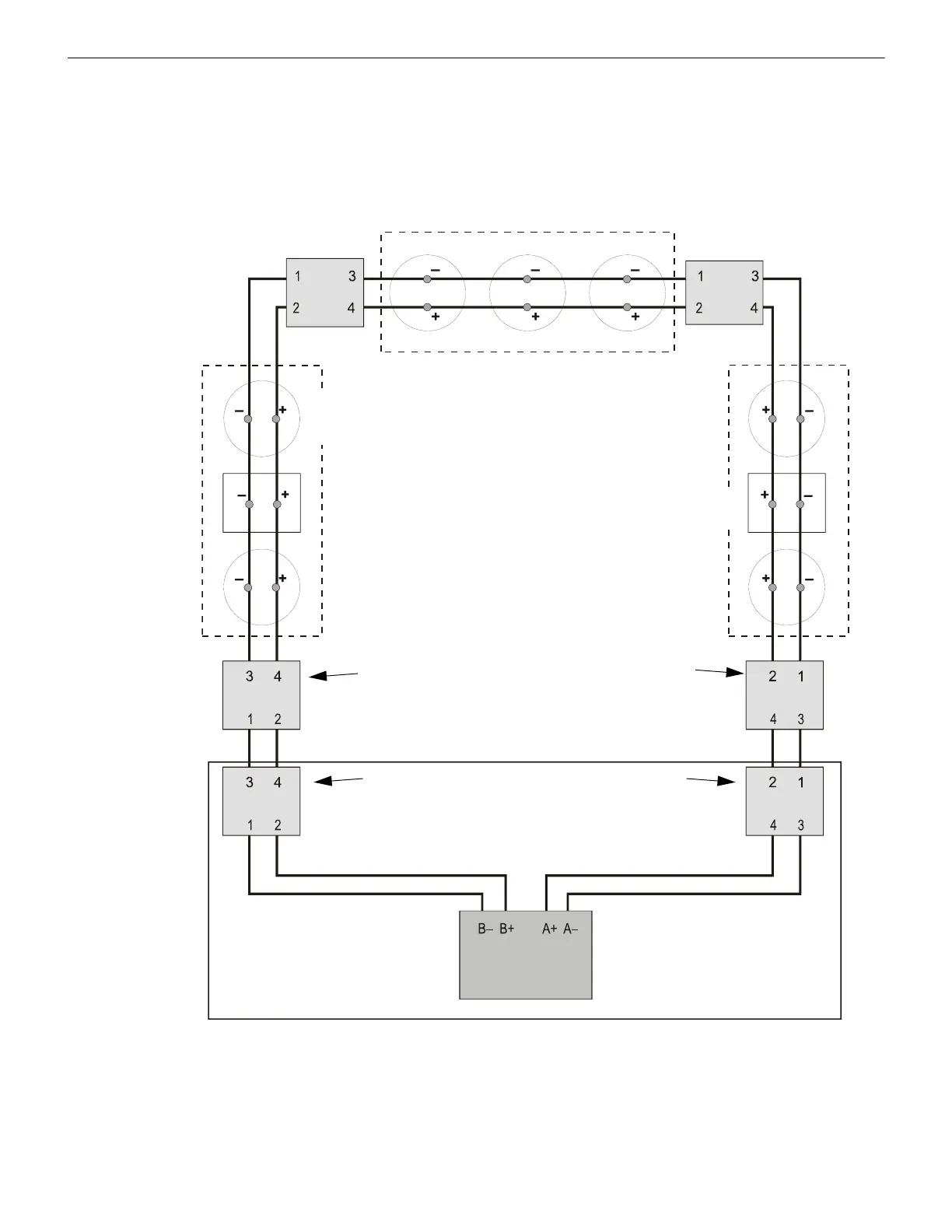
5.5 NFPA Class A SLC Using Isolator Modules
A variation of Class A operation using isolator modules to protect a section of the SLC. By flanking each group of devices with
fault isolator modules each group is protected from faults that may occur in the other groups. For example, a fault in Section B will not
affect Sections A & C. The isolator modules on either side of Section B will open the loop. Section A will still operate from power on the
SLC Out side and Section C will operate from the SLC Return side.
• A combination of isolator modules and isolator bases may be used.
• T-tapping is NOT allowed within the Class A configuration.
• Isolator modules shall be within 20 ft. (6.1 m) of device and the wire must be enclosed in metal conduit.
SLC Out SLC Return
SLC-style6iso.wmf
Control Panel
Two-wire
Addressable
Detector
Addressable
Pull Station
Section B
Section C
Section A
AFP-100, AFP-200, AM2020/AFP1010,
System 5000 with AIM-200: The first
isolator module on SLC Out and SLC
Return must be contained within the same
enclosure as the FACP, or these isolator
modules must be connected within 20 ft.
(6.1 m) of the FACP enclosure in conduit.
Isolator
Module
Isolator
Module
Isolator
Module
The first isolator module on SLC Out and SLC Return is
optional for the N16, NFS-320, NFS2-640, NFS2-3030,
NFS-640, NFS-3030, AFP-300, and AFP-400 because the
panels provide the functionality.
Additional isolator module required when first device in the
section is more than 20 feet from the control panel.
Figure 5.6 NFPA Class A SLC Using Isolator Modules
Isolator
Module
Isolator
Module
Isolator
Module

 Loading...


