Notifier SLC Wiring Manual — P/N 51253:U9 12/3/2021 63
Power Connections: Powered by the SLC Intelligent Detectors, Intelligent Detector Bases, and Wireless Gateway
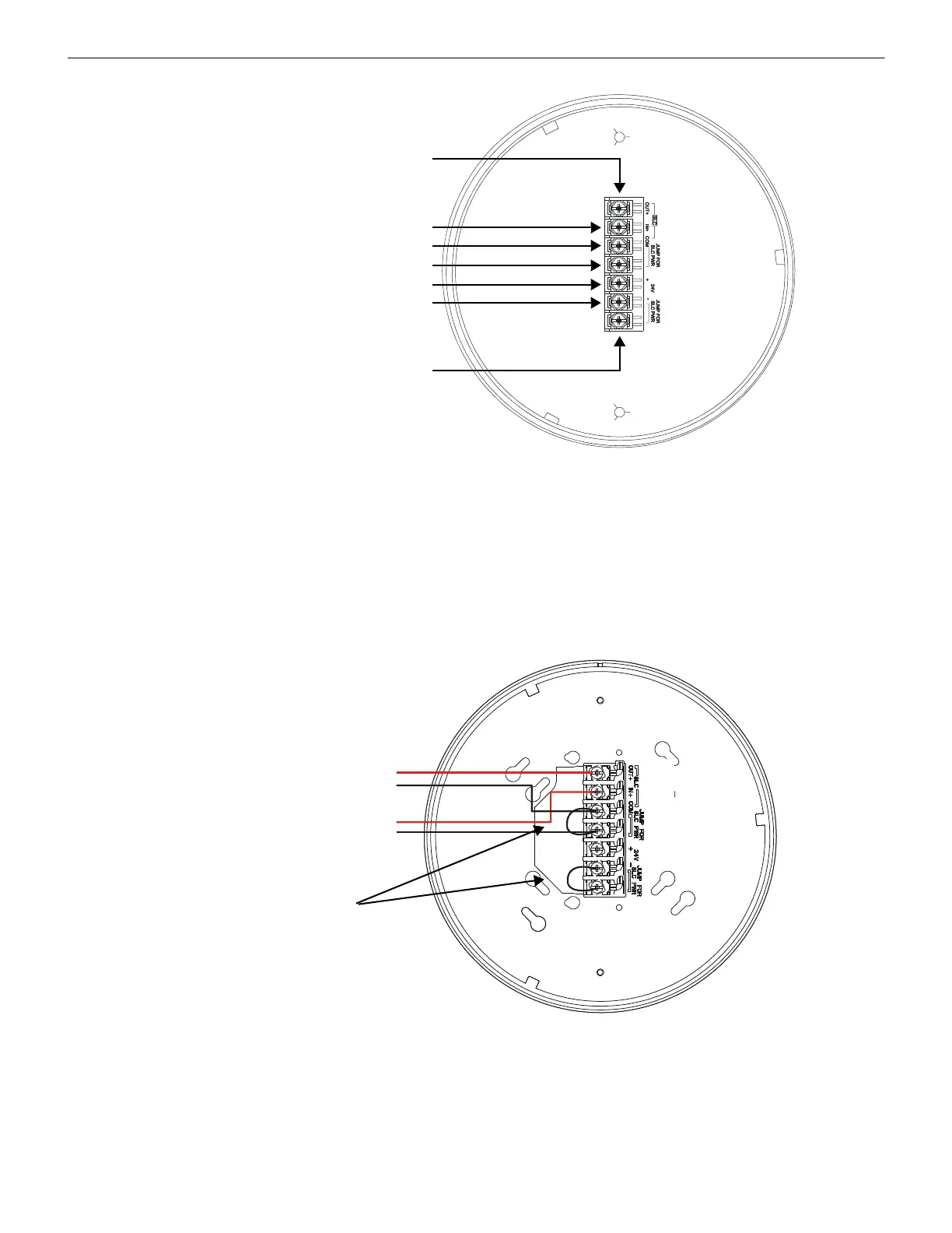
10.8 Power Connections: Powered by the SLC
The FWSG(A) provides isolation of short circuits on the SLC in Class A installations. SLC connections are power-limited by the panel.
An interruption in the SLC that causes a loss of power at the FWSG(A) for more than 100ms may result in a trouble condition and loss
of fire protection provided by the wireless devices for approximately 15 minutes. Use of an external +24V power source (not SLC
power) is recommended for installations that require fire protection in the presence of short circuits, including Class A applications and
applications that use isolator modules. Figure 10.14 shows typical wiring of a Wireless Network Gateway connected to an SLC when
power is supplied by the SLC loop.
A7 SLC OUT+/In+
A6 SLC IN+/OUT+
A5 SLC- (Common)
A4 SLC Power Select 2
A3 Power +24VDC
A2 Power Ground
A1 SLC Power- Select 1
Figure 10.13 FWSG Mounting Plate - Terminal Layout
2
.
4
.
w
m
f
SLC in from FACP/device
SLC out to next device (Class B)
or SLC back to FACP (Class A)
Jumpers
2
.
5
.
w
m
f
Figure 10.14 FWSG Wiring Diagram, Powered by SLC Loop
A7
A6
A5

 Loading...


