124 6820 / 6820EVS Manual P/N LS10144-001SK-E:C 09/28/2017
9.5.3 Point Programming For Internal or External Power Module
To program for an internal or external power module points:
1. Enter the installer code. The panel will automatically go to the main menu.
2. Select 7 for Program Menu.
3. Press 4 to enter point menu.
4. Press the up or down arrows to select the desired module. Refer to Section 9.5.3 for available choices, then press ENTER.
5. Enter the number of the circuit or point you wish to edit. Refer to Table 9.5 for available selections, then press ENTER.
6. Select the type by pressing the up or down arrows, then press ENTER.
7. Select the function by pressing the up or down arrows, then press ENTER.
8. Select the group by pressing the up or down arrows, then press ENTER.
9. Edit point name. See Section Appendix B. Or, press the right arrow to skip point name edit.
SWITCH
(cont.)
EVS INPUT Latching User also has EVS Event Number 1-8 option for EVS INPUT.
Only available when an EVS-VCM is installed in the system.
Non Latching
EVS TAMPER Latching
Non Latching
EVS SUPER-
VISORY
Latching
Non Latching
CO DETECT
SWITCH
CO Detector Switch
CO
SUPERVISORY
DETECT SWITCH
Latching CO Supervisory Detector Switch
Non Latching
NOTIF
OUTPUT PT Select Group Output point, a general use notification type. Use for driving
standard notification appliances.
AUX CONST Use constant power for applications that require a constant auxiliary
power source. Power is always present at constant circuits.
AUX RESET Use for auxiliary power, resettable applications. See Section 4.16.3
for a description of how this option operates.
AUX DOOR Use for auxiliary power, door holder applications. For example, if
you were using an auxiliary power supply for door holders, you
would use this option. See Section 4.16.3 for a description of how
this option operates.
RELAY
OUTPUT PT Select Group Output point, a general use relay type. Use for applications requiring
a relay, such as fan shutdown, elevator recall, and so on.
AUX RESET Use for auxiliary power, resettable applications. See Section 4.16.3
for a description of how this option operates.
AUX DOOR Use for auxiliary power, door holder applications. For example, if
you were using an auxiliary power supply for door holders, you
would use this option. See Section 4.16.3 for a description of how
this option operates.
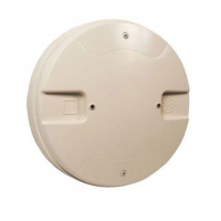
W-GATEWAY
W-SWITCH Same as SWITCH
W-RELAY
Same as RELAY When a wireless relay is in use, module device count must be
limited to 109 modules per loop. This includes wired and wireless
modules that are on the same loop. The module address must be
within 1-109.
Type Selection Function Latching Option Comments
Table 9.4 Point Programming for 6815
 Loading...
