6820 / 6820EVS Manual P/N LS10144-001SK-E:C 09/28/2017 95
7.9.1 SLC Devices with DIP Switches
Input and relay module addresses are set using the DIP switches on the module board. The chart below shows the available addresses.
For example, to select address 3, place DIP switches 1 and 2 in the up position. The range of valid addresses is 1-127. 0 is an invalid
address.
Figure 7.8 SD SLC Device Addressing Using DIP Switches
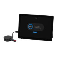
7.10 SK-WGI Wireless Gateway
For more information regarding Gateway wiring instructions, see SWIFT manual LS10036-000SK-E.
7.10.1 Power Connections for the Gateway
The SK-WGI Wireless Gateway acts as a bridge between a group of wireless fire devices and a SLC loop on the 6820/EVS. It is powered
by the SLC loops or by a regulated, external 24 VDC UL listed power supply. See the SWIFT
®
Smart Wireless Integrated Fire Technol-
ogy Instruction Manual P/N LS10036-000SK-E for a list of available wireless devices, system setup, and operation
NOTE: The SK-WGI, as part of the wireless network, has been tested for compliance with the Federal Communications Commission (FCC)
requirements of the United States Government. It has not been evaluated for use outside the USA. Use of this system outside the USA is subject
to local laws and rules to which this product may not conform. It is the sole responsibility of the user to determine if this product may be legally
used outside the USA.
NOTE: It is recommended to use the same wire gauge if there are multiple connections to the same terminal.

 Loading...