6820 / 6820EVS Manual P/N LS10144-001SK-E:C 09/28/2017 17
3.4 Electrical Specifications
Terminal Label Description
Rating
Earth Ground
Faults
Voltage Current
L AC input (hot) 120 VAC, 60 Hz 3.3 A N/A
Earth ground N/A N/A N/A
N AC input (neutral) 120 VAC, 60 Hz 3.3 A N/A
– NAC 6 Flexput™ Circuits 24 VDC 3.0A notification and auxiliary
power circuits
0
+ 100 mA for initiation circuits
– NAC 5 Flexput™ Circuits 24 VDC 3.0A notification and auxiliary
power circuits
0
+ 100 mA for initiation circuits
– NAC 4 NAC Circuits 24 VDC 3.0A notification and auxiliary
power circuits
0
+
– NAC 3 NAC Circuits 24 VDC 3.0A notification and auxiliary
power circuits
0
+
– NAC 2 NAC Circuits 24 VDC 3.0A notification and auxiliary
power circuits
0
+
– NAC 1 NAC Circuits 24 VDC 3.0A notification and auxiliary
power circuits
0
+
B SBUS OUT SBUS communication 5 VDC 100 mA 0
A
+ SBUS power 24 VDC 1.0 A
-
B SBUS IN Used for Class A installations 0
A
+
-
B EXT. Comm Cellular Connection input 0
A
+ 55 mA, 100 mA
-
N.C. RELAY 1 General Purpose Relay 1 24 VDC 2.5 A, resistive N/A
C
N.O.
N.C. RELAY 2 General Purpose Relay 2 24 VDC 2.5 A, resistive N/A
C
N.O.
N.C. TROUBLE Trouble Relay 24 VDC 2.5 A, resistive N/A
C
N.O.
SC- L1
SLC OUT
SLC terminals 32 VDC 150 mA 0
SC+
SC- SLC Programming Terminal
(-)
32 VDC 150 mA 0
SC+ SLC Programming Terminal
(+)
32 VDC 150 mA
SC- L2
SLC IN
Used for Class A installations 0
SC+
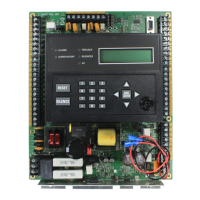
Table 3.1 Terminal Descriptions and Electrical Specification

 Loading...


