6820 / 6820EVS Manual P/N LS10144-001SK-E:C 09/28/2017 41
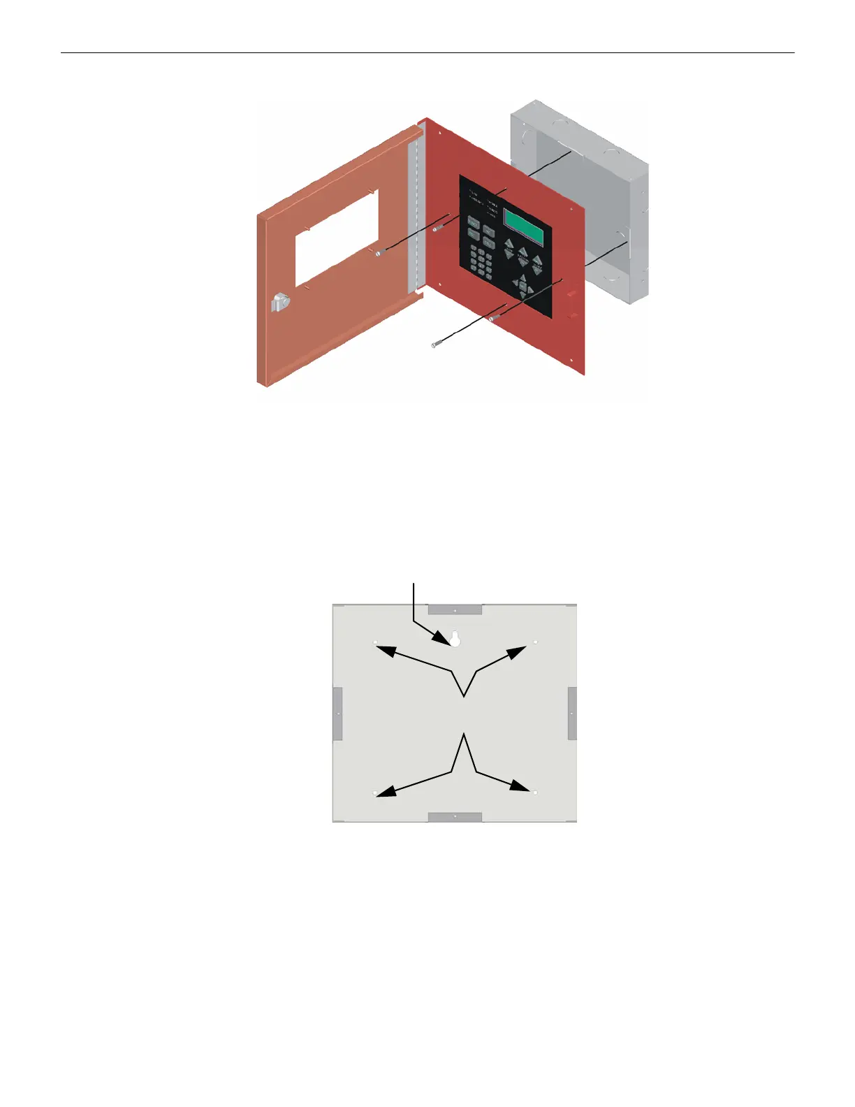
4. Attach the annunciator and door assembly to back box as shown in Figure 4.19 using the supplied screws.
Figure 4.19 Attaching Annunciator/Door Assembly to Backbox
Surface Mounting
The optional Model RA-100TG/TR trim ring kit is available for use when surface mounting.
1. Remove the desired knock out.
2. To properly mount the back box, insert a single screw into the key shaped mounting hole. Do not tighten all the way. See
Figure 4.20.
Place a level on top of the back box, with the back box level insert the rest of the mounting screws.
Figure 4.20 Back Box Surface Mount Holes
3. Run wires to the control panel.
Key Shaped
Mounting Hole
Back Box
Mounting Holes

 Loading...