Connection
1.
Connect the Coupling head "Brake" (yel-
low) rst.
2.
Then connect the Coupling head "Provi-
sion" (red).
3. Release the parking brake.
Unhitching
1. Apply the parking brake.
2.
Disconnect the Coupling head "Provision"
(red) rst.
3.
Then disconnect the Coupling head
"Brake" (yellow).
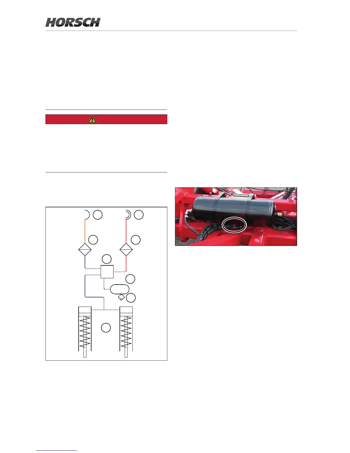
Maintenance
¾ Drain the air reservoir every day during operation.
Air vessel with drain valve
¾ Clean the pipeline lters whenever required,
but at least once every year.
¾ Readjust the brake when required:
In braking position the brake lever should be
under an engle of 90° to the fork.
In released position the brake lever should
touch the fork at the front and the wheels
should be able to turn freely.
¾ To ensure the function of the valves, anti-
freeze should be mixed into the compressed
air. Follow the operating instructions of the
tractor!
¾ The coupling heads should be closed with
blanking covers or a plastic bag to protect
against damage caused by moisture.
¾ Release the brake Brake pads may otherwise
stick to the drum and make restarting of the
machine more dicult.
Optional equipment
Brake system
The machine can be equipped with a pneumatic
or a hydraulic brake system. The machine is
equipped with a parking brake for safe parking
DANGER
Uncontrolled rolling of the machine can cause
severe injuries by crushing or rolling over..
¾ Park the machine only on level ground with
sucient load bearing capacity.
¾ Secure the machine with wheel chocks
against rolling before releasing the brake.
Pneumatic brake
The pneumatic brake is a dual-line single-circuit
braking system with pressure regulator.
 Loading...