112
• To ensure communication security and avoid broadcast storms, VLANs are configured in the
enterprise network to isolate Layer 2 traffic of different departments. VLAN 100 is assigned to
Department A, and VLAN 200 is assigned to Department B.
• Ensure that hosts within the same VLAN can communicate with each other. Host A can communicate
with Host C, and Host B can communicate with Host D.
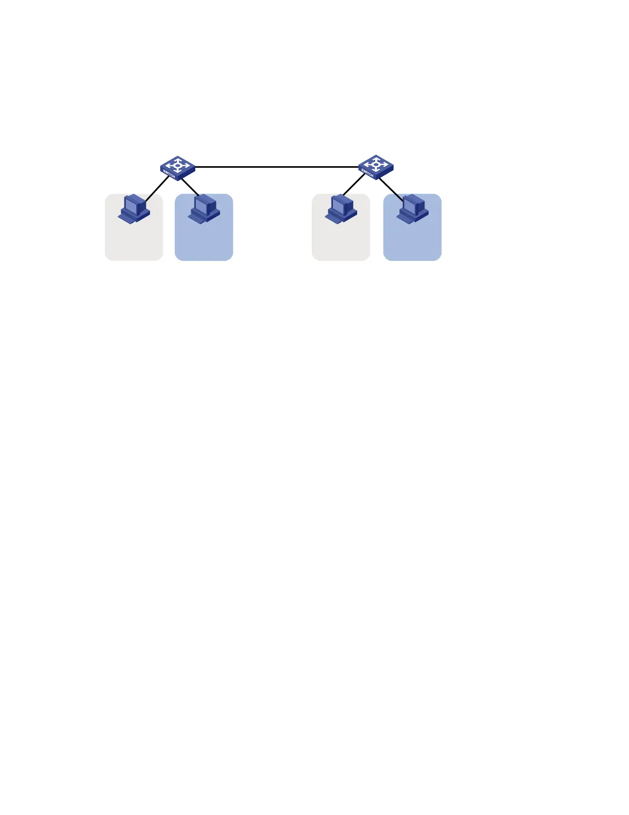
Figure 37 Network diagram for port-based VLAN configuration
GE1/0/2GE1/0/1
Host A Host CHost B Host D
Device A
VLAN 100 VLAN 100VLAN 200 VLAN 200
Device B
GE1/0/1 GE1/0/2
GE1/0/3 GE1/0/3
Configuration procedure
1. Configuration on Device A
# Create VLAN 100, and assign port GigabitEthernet 1/0/1 to VLAN 100.
<DeviceA> system-view
[DeviceA] vlan 100
[DeviceA-vlan100] port gigabitethernet 1/0/1
[DeviceA-vlan100] quit
# Create VLAN 200, and assign port GigabitEthernet 1/0/2 to VLAN 200.
[DeviceA] vlan 200
[DeviceA-vlan200] port gigabitethernet 1/0/2
[DeviceA-vlan200] quit
# Configure port GigabitEthernet 1/0/3 as a trunk port, and assign it to VLANs 100 and 200, enabling
GigabitEthernet 1/0/3 to forward traffic of VLANs 100 and 200 to Device B.
[DeviceA] interface gigabitethernet 1/0/3
[DeviceA-GigabitEthernet1/0/3] port link-type trunk
[DeviceA-GigabitEthernet1/0/3] port trunk permit vlan 100 200
Please wait... Done.
2. Configure Device B as you configure Device A.
3. Configure Host A and Host C to be on the same network segment, 192.168.100.0/24 for
example. Configure Host B and Host D to be on the same network segment, 192.168.200.0/24
for example.
Verification
1. Host A and Host C and ping each other successfully, but they both fail to ping Host B. Host B and
Host D and ping each other successfully, but they both fail to ping Host A.
2. Check whether the configuration is successful by displaying relevant VLAN information.
# Display information about VLANs 100 and 200 on Device A:
[DeviceA-GigabitEthernet1/0/3] display vlan 100
VLAN ID: 100
VLAN Type: static

 Loading...


