180
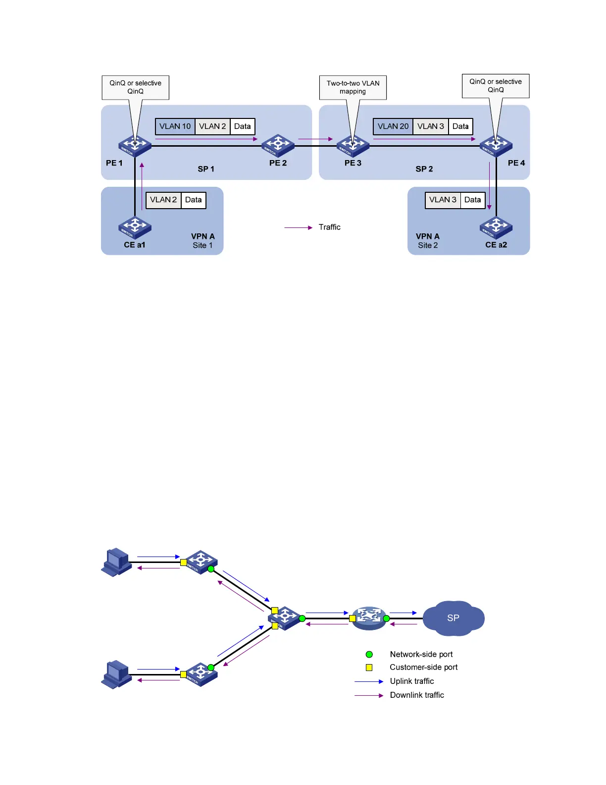
Figure 59 Application scenario of two-to-two VLAN mapping
Site 1 and Site 2 are in VLAN 2 and VLAN 3, respectively. The VLAN assigned for VPN A is VLAN 10 in
the SP 1 network and VLAN 20 in the SP 2 network.
If Site 1 sends a packet to Site 2, the packet is processed on the way to its destination using the following
workflow:
1. When the packet tagged with VLAN 2 arrives at the edge of network SP 1, PE 1 tags the packet
with outer VLAN 10 by using QinQ or selective QinQ.
2. When the double-tagged packet enters the SP 2 network, PE 3 replaces the outer VLAN tag (VLAN
10) with VLAN 20. Because the packet is destined for Site 2 in VLAN 3, PE 3 also replaces the
inner tag (VLAN 2) of the packet with VLAN 3. This process is two-to-two VLAN mapping.
3. When PE4 receives the packet with the new VLAN tag pair, it removes the outer VLAN tag and
forwards the packet to VLAN 3.
For more information about QinQ and selective QinQ, see the chapter “QinQ configuration.”
Concepts and terms
Figure 60 shows a simplified network to help explain the concepts and terms that you may encounter
when working with VLAN mapping.
Figure 60 Basic concepts of VLAN mapping

 Loading...


