179
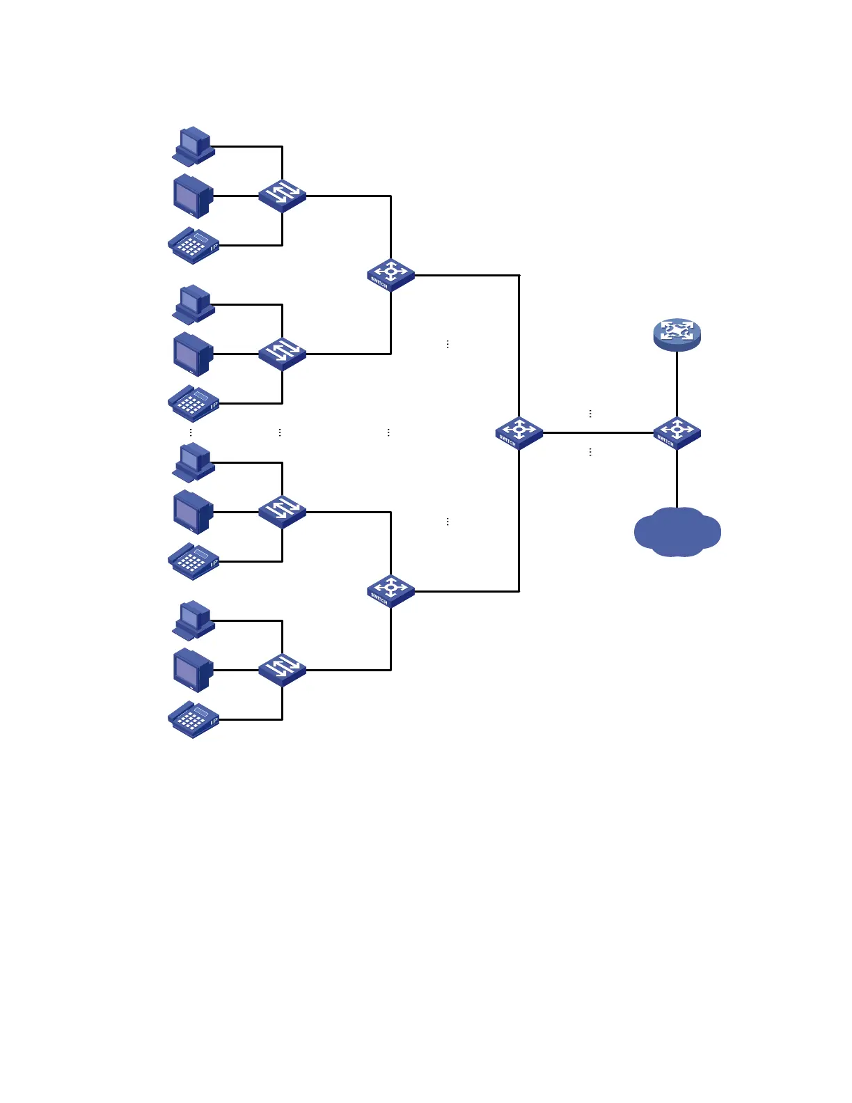
Figure 58 Application scenario of one-to-one and many-to-one VLAN mapping
VLAN 101 - 102 - > VLAN 501
VLAN 201 - 202 - > VLAN 502
VLAN 301 - 302 - > VLAN 503
Campus switch
Distribution
network
DHCP client
DHCP server
Wiring - closet
switch
VLAN 1 - > VLAN 101
VLAN 2 - > VLAN 201
VLAN 3 - > VLAN 301
VLAN 1 - > VLAN 102
VLAN 2 - > VLAN 202
VLAN 3 - > VLAN 302
PC
VoD
VoIP
VLAN 2
Home gateway
VLAN 1
VLAN 3
PC
VoD
VoIP
VLAN 2
Home gateway
VLAN 1
VLAN 3
Wiring-closet
switch
VLAN 1 - > VLAN 199
VLAN 2 - > VLAN 299
VLAN 3 - > VLAN 399
VLAN 1 -> VLAN 200
VLAN 2 -> VLAN 300
VLAN 3 -> VLAN 400
PC
VoD
VoIP
VLAN 2
Home gateway
VLAN 1
VLAN 3
PC
VoD
VoIP
VLAN 2
Home gateway
VLAN 1
VLAN 3
VLAN 199 - 200 - > VLAN 501
VLAN 299 - 300 - > VLAN 502
VLAN 399 - 400 - > VLAN 503
To further sub-classify each type of traffic by customer, perform one-to-one VLAN mapping on the wiring-
closet switches, assigning a separate VLAN for each type of traffic from each customer. The required total
number of VLANs in the network can be very large. To prevent the maximum number of VLANs from
being exceeded on the distribution layer device, perform many-to-one VLAN mapping on the campus
switch to assign the same type of traffic from different customers to the same VLAN.
Application scenario of two-to-two VLAN mapping
Figure 59 shows a typical application scenario in which two remote sites of VPN A, Site 1 and Site 2,
must communicate across two SP networks, SP 1 and SP 2.

 Loading...


