218
LLDP configuration examples
Basic LLDP configuration example
Network requirements
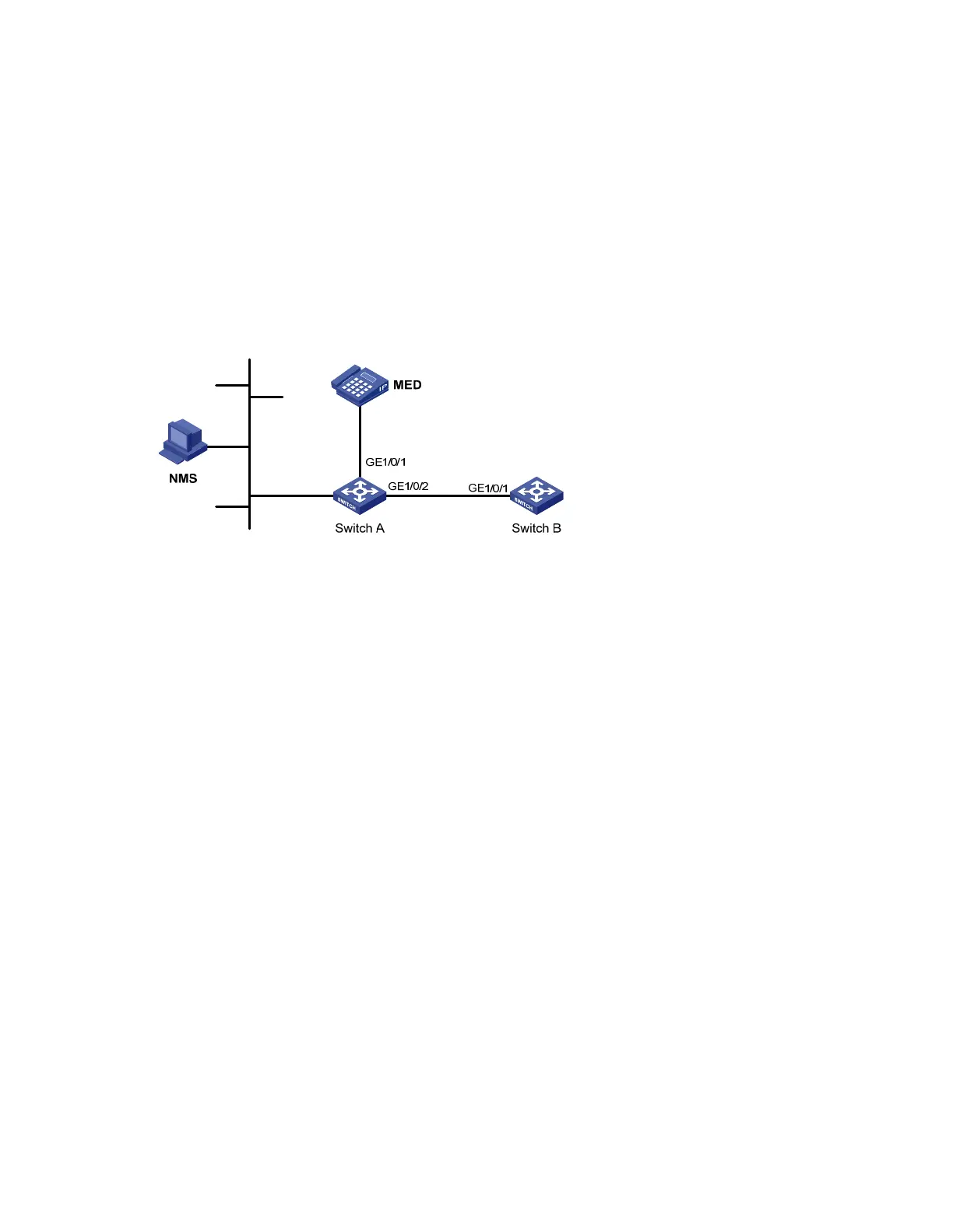
As shown in Figure 70, the NMS and Switch A are located in the same Ethernet. An MED device and
Switch B are connected to GigabitEthernet 1/0/1 and GigabitEthernet 1/0/2 of Switch A.
Enable LLDP on the ports of Switch A and Switch B to monitor the link between Switch A and Switch B
and the link between Switch A and the MED device on the NMS.
Figure 70 Network diagram for basic LLDP configuration
Configuration procedure
1. Configure Switch A
# Enable LLDP globally (you can skip this step because LLDP is enabled globally by default).
<SwitchA> system-view
[SwitchA] lldp enable
# Enable LLDP on GigabitEthernet 1/0/1 and GigabitEthernet 1/0/2 (you can skip this step because
LLDP is enabled on ports by default), and set the LLDP operating mode to Rx.
[SwitchA] interface gigabitethernet 1/0/1
[SwitchA-GigabitEthernet1/0/1] lldp enable
[SwitchA-GigabitEthernet1/0/1] lldp admin-status rx
[SwitchA-GigabitEthernet1/0/1] quit
[SwitchA] interface gigabitethernet 1/0/2
[SwitchA-GigabitEthernet1/0/2] lldp enable
[SwitchA-GigabitEthernet1/0/2] lldp admin-status rx
[SwitchA-GigabitEthernet1/0/2] quit
2. Configure Switch B
# Enable LLDP globally (you can skip this step because LLDP is enabled globally by default).
<SwitchB> system-view
[SwitchB] lldp enable
# Enable LLDP on GigabitEthernet1/0/1 (you can skip this step because LLDP is enabled on ports by
default), and set the LLDP operating mode to Tx.
[SwitchB] interface gigabitethernet 1/0/1
[SwitchB-GigabitEthernet1/0/1] lldp enable
[SwitchB-GigabitEthernet1/0/1] lldp admin-status tx

 Loading...


