129
Super VLAN configuration example
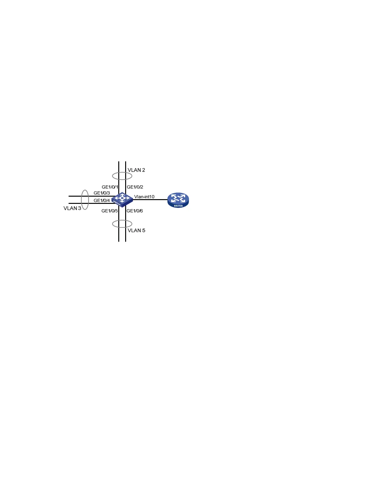
Network requirements
As shown in Figure 41,
• Create super VLAN 10, and configure the IPv4 address and IPv6 address of its VLAN interface as
10.0.0.1/24 and 2001::1/64.
• Create the sub-VLANs VLAN 2, VLAN 3, and VLAN 5.
• Assign GigabitEthernet 1/0/1 and GigabitEthernet 1/0/2 to VLAN 2, GigabitEthernet 1/0/3 and
GigabitEthernet 1/0/4 to VLAN 3, and GigabitEthernet 1/0/5 and GigabitEthernet 1/0/6 to
VLAN 5.
• The sub-VLANs are isolated at Layer 2 but connected at Layer 3.
Figure 41 Network diagram for super-VLAN configuration
Configuration procedure
# Create VLAN 10.
<Sysname> system-view
[Sysname] vlan 10
[Sysname-vlan10] quit
# Create VLAN-interface 10, and configure the IPv4 address and IPv6 address of VLAN-interface 10 as
10.0.0.1/24 and 2001::1/64.
[Sysname-vlan10] interface vlan-interface 10
[Sysname-Vlan-interface10] ip address 10.0.0.1 255.255.255.0
[Sysname-Vlan-interface10] ipv6 address 2001::1/64
# Enable local proxy ARP on VLAN interface 10, so that IPv4 packets can be exchanged between sub-
VLANs at Layer 3.
[Sysname-Vlan-interface10] local-proxy-arp enable
# Enable local proxy ND on VLAN interface 10, so that IPv6 packets can be exchanged between sub-
VLANs at Layer 3.
[Sysname-Vlan-interface10] local-proxy-nd enable
[Sysname-Vlan-interface10] quit
# Create VLAN 2, and assign GigabitEthernet 1/0/1 and GigabitEthernet 1/0/2 to it.
[Sysname] vlan 2
[Sysname-vlan2] port gigabitethernet 1/0/1 gigabitethernet 1/0/2
[Sysname-vlan2] quit

 Loading...


