202
Chapter 7, Configure Screen
Field Descriptions
Field Descriptions
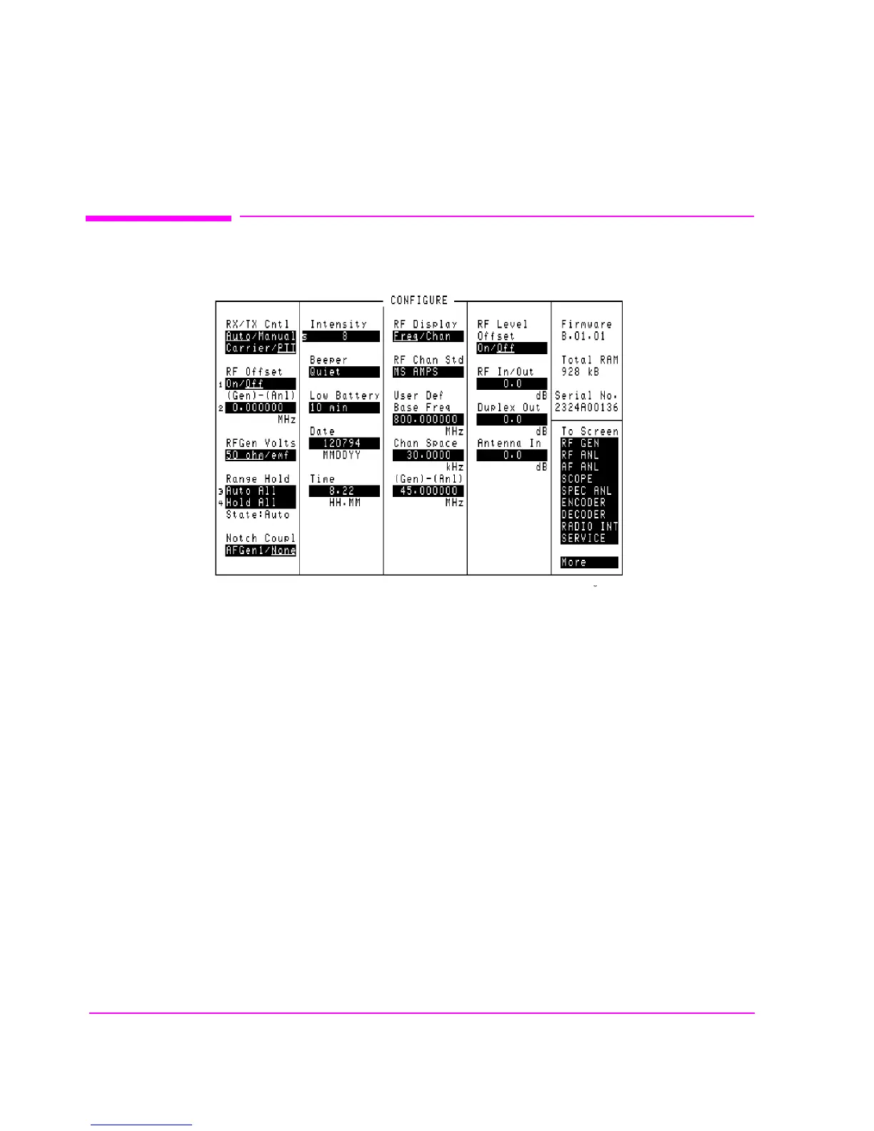
Figure 39 The Configure Screen
Antenna In
This field is used to indicate losses or gains between the ANT IN port and the
device-under-test.
Enter a positive value to indicate a gain (such as an amplifier). The Spectrum
Analyzer’s marker level (
Lvl) measurement is automatically reduced by that
amount. The Spectrum Analyzer’s Ref Level is automatically decreased by the
same amount, so the trace position does not appear to change.
Enter a negative value to indicate a loss (such as cable loss). The Spectrum
Analyzer Marker’s Level (
Lvl) measurement is automatically increased by that
amount. The Spectrum Analyzer’s Ref Level is automatically increased by the
same amount, so the trace position does not appear to change.
cnfgscrn.wmf