Removal and replacement procedures 50
4.
Disengage and extend the following components approximately 8 cm (3 in):
o Half-height and full-height blades ("Half-height or full-height blade" on page 34)
o Power supplies ("HP BladeSystem c7000 power supply or power supply blank" on page 30)
5. Remove the fans ("Active Cool 200 fan" on page 39).
6. Remove the interconnect switches and Pass-Thru modules ("Interconnect switch or Pass-Thru module" on
page 40).
7. Remove the Onboard Administrator modules ("Onboard Administrator" on page 43).
Remove the Onboard Administrator tray ("Onboard Administrator tray" on page 43).
8. Remove the rear cage ("Rear cage" on page 45).
WARNING: To reduce the risk of personal injury or equipment damage, at least two people are
needed to safely move the rear cage.
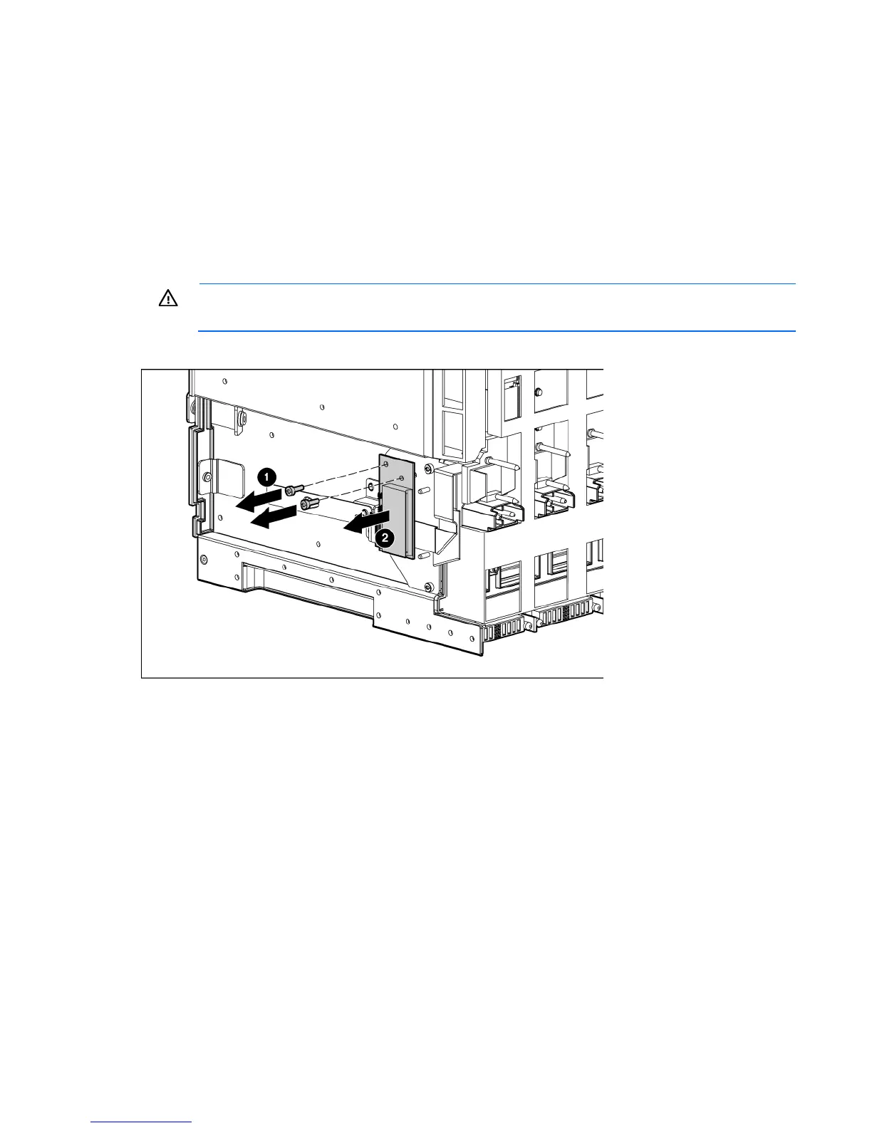
9. Remove the two T-15 Torx screws that secure the pass-thru board.

 Loading...


