Removal and replacement procedures 45
5.
Configure the AC input module. For more information, see "Midplane assembly (on page 53)."
To replace the component, reverse the removal procedure.
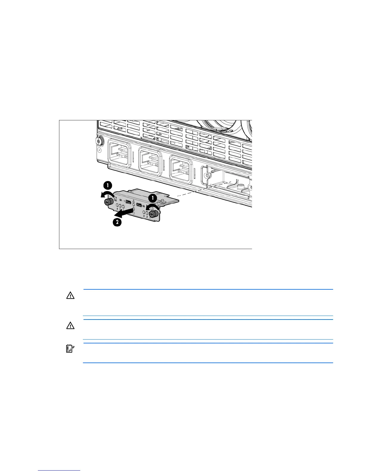
AC control module
To remove the component:
1. Disconnect all USB connections from the Onboard Administrator to the control module.
2. Loosen the two slotted screws that secure the control module.
3. Remove the control module.
To replace the component, reverse the removal procedure.
Rear cage
WARNING: To reduce the risk of damage to the midplane and component connectors, always
remove or disengage and extend all blades and power supplies approximately 8 cm (3 in) before
removing or installing the rear cage.
WARNING: To reduce the risk of personal injury or equipment damage, at least two people are
needed to safely move the rear cage.
IMPORTANT: When removing components from the rear cage, note their position for later
replacement.
To remove the component:
1. Power down the server blades ("Power down the server blades or workstation blades" on page 28).
2. Power down the enclosure (on page 29).
3. Disconnect all cables.
4. Disengage and extend the following components approximately 8 cm (3 in):
o Half-height and full-height blades ("Half-height or full-height blade" on page 34)
 Loading...


