Component identification 70
Server blade signal
Interconnect bay
number
Interconnect bay label
NICs 1, 2, 3, and 4
(embedded)
1, 2
Mezzanine 1
3, 4
5, 6 and then 7, 8
Mezzanine 3
7, 8 and then 5, 6
NOTE: For information on the location of LEDs and ports on individual interconnect modules, see
the documentation that ships with the interconnect module.
If a four-port option card is installed in mezzanine slot 2, then ports 1 and 2 are connected to interconnect
bays 5 and 6, respectively, and ports 3 and 4 are connected to interconnect bays 7 and 8, respectively.
If a four-port option card is installed in mezzanine slot 3 in a full-height server blades or workstation blades,
then ports 1 and 2 are connected to interconnect bays 7 and 8, respectively, and ports 3 and 4 are
connected to interconnect bays 5 and 6, respectively.
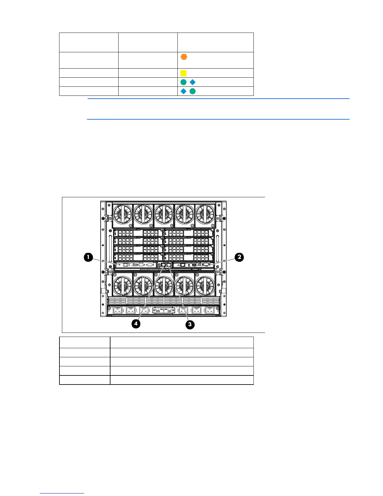
Onboard Administrator components
Item Description
Onboard Administrator bay 1
2
Onboard Administrator bay 2 (redundant, if used)
3
Enclosure link-up port
4
Enclosure link-down port
 Loading...


