EasyManuals Logo

HP BladeSystem c7000 Maintenance And Service Guide

HP BladeSystem c7000
80 pages
To Next Page IconTo Next Page
To Previous Page IconTo Previous Page
Page #44 background imageLoading...
Page #44 background image
Removal and replacement procedures 44
4.
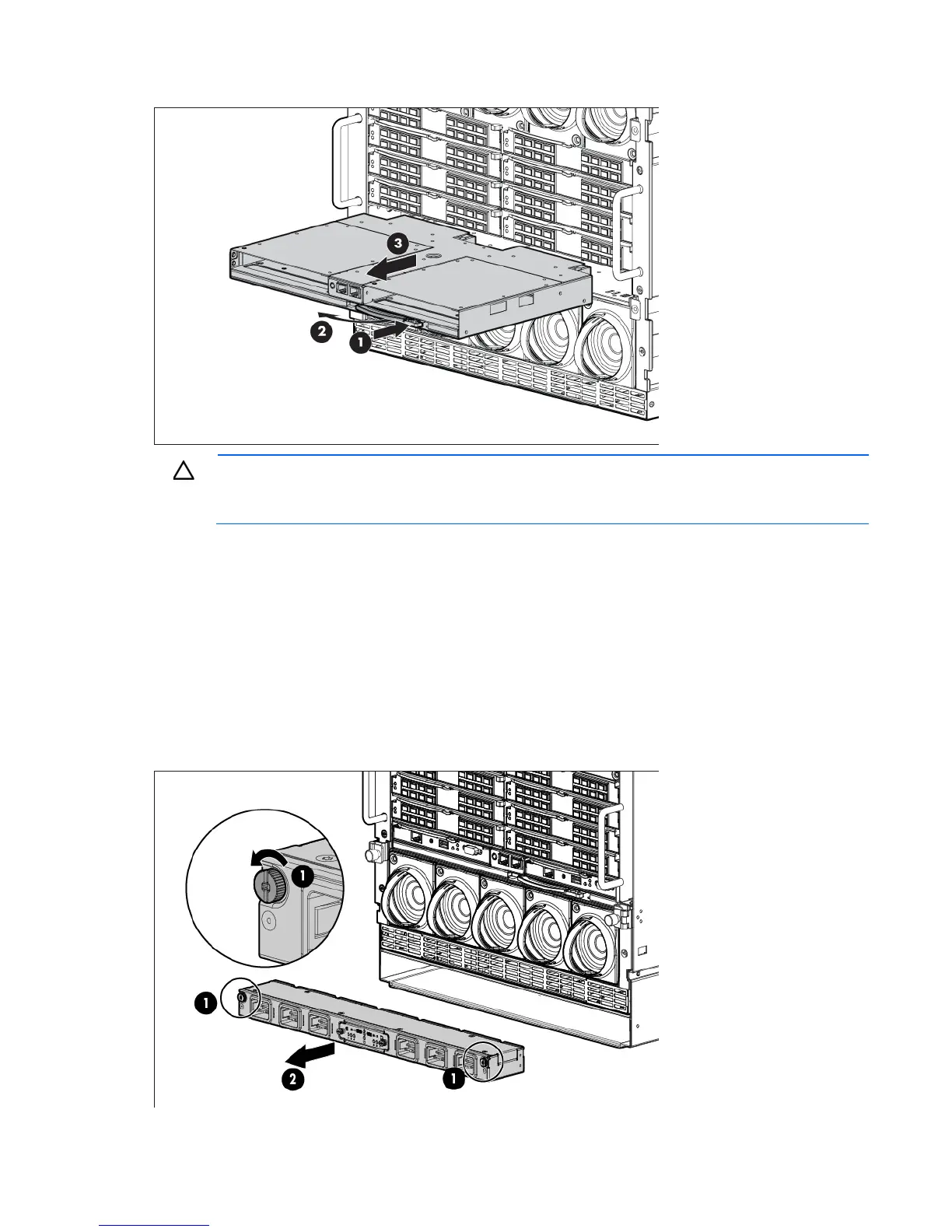
Remove the Onboard Administrator tray.
CAUTION: For best cooling practices, do not operate the enclosure for extended periods with
more than one component or blank removed. When removing an active component, replace it
with a blank.
To replace the component, reverse the removal procedure.
AC input module
To remove the component:
1. Power down the server blades ("Power down the server blades or workstation blades" on page 28).
2. Power down the enclosure (on page 29).
3. Loosen the two slotted T-15 Torx screws that secure the AC input module.
4. Remove the AC input module.

Table of Contents

Other manuals for HP BladeSystem c7000

Questions and Answers:

Question and Answer IconNeed help?

Do you have a question about the HP BladeSystem c7000 and is the answer not in the manual?

HP BladeSystem c7000 Specifications

General IconGeneral
Form Factor10U
Number of Bays16
Redundant PowerYes
Redundant FansYes
Maximum Blade Servers16 half-height or 8 full-height
Operating Temperature10° to 35°C (50° to 95°F)
Power SuppliesUp to 6
Cooling Fans10
ManagementOnboard Administrator
Interconnect ModulesUp to 8
Networking OptionsEthernet, Fibre Channel, InfiniBand
CompatibilityHP ProLiant and Integrity server blades
Relative Humidity10% to 90% (non-condensing)

Related product manuals