EasyManuals Logo

HP BladeSystem c7000 Maintenance And Service Guide

HP BladeSystem c7000
80 pages
To Next Page IconTo Next Page
To Previous Page IconTo Previous Page
Page #64 background imageLoading...
Page #64 background image
Component identification 64
Component identification
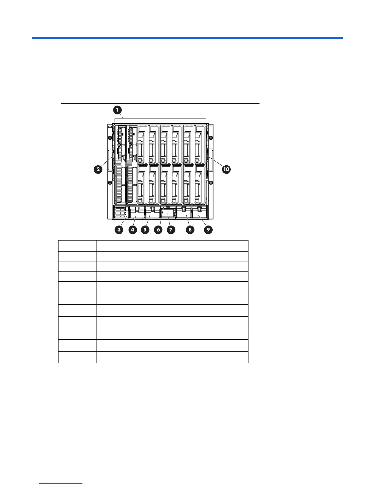
Enclosure front components
Item Description
1
Device bays*
2
Air intake slot (Do not block.)
3
Power supply bay 1
4
Power supply bay 2
5
Power supply bay 3
6
Power supply bay 4
7
Insight Display
8
Power supply bay 5
9
Power supply bay 6
10
Air intake slot (Do not block.)
*For more information, see "Device bay numbering (on page 64)."
Device bay numbering
Each enclosure requires interconnects to provide network access for data transfer. Interconnects reside in
bays located on the rear of the enclosure. Be sure to review device bay numbering to determine which
external network connections on the interconnects are active.

Table of Contents

Other manuals for HP BladeSystem c7000

Questions and Answers:

Question and Answer IconNeed help?

Do you have a question about the HP BladeSystem c7000 and is the answer not in the manual?

HP BladeSystem c7000 Specifications

General IconGeneral
Form Factor10U
Number of Bays16
Redundant PowerYes
Redundant FansYes
Maximum Blade Servers16 half-height or 8 full-height
Operating Temperature10° to 35°C (50° to 95°F)
Power SuppliesUp to 6
Cooling Fans10
ManagementOnboard Administrator
Interconnect ModulesUp to 8
Networking OptionsEthernet, Fibre Channel, InfiniBand
CompatibilityHP ProLiant and Integrity server blades
Relative Humidity10% to 90% (non-condensing)

Related product manuals