Removal and replacement procedures 49
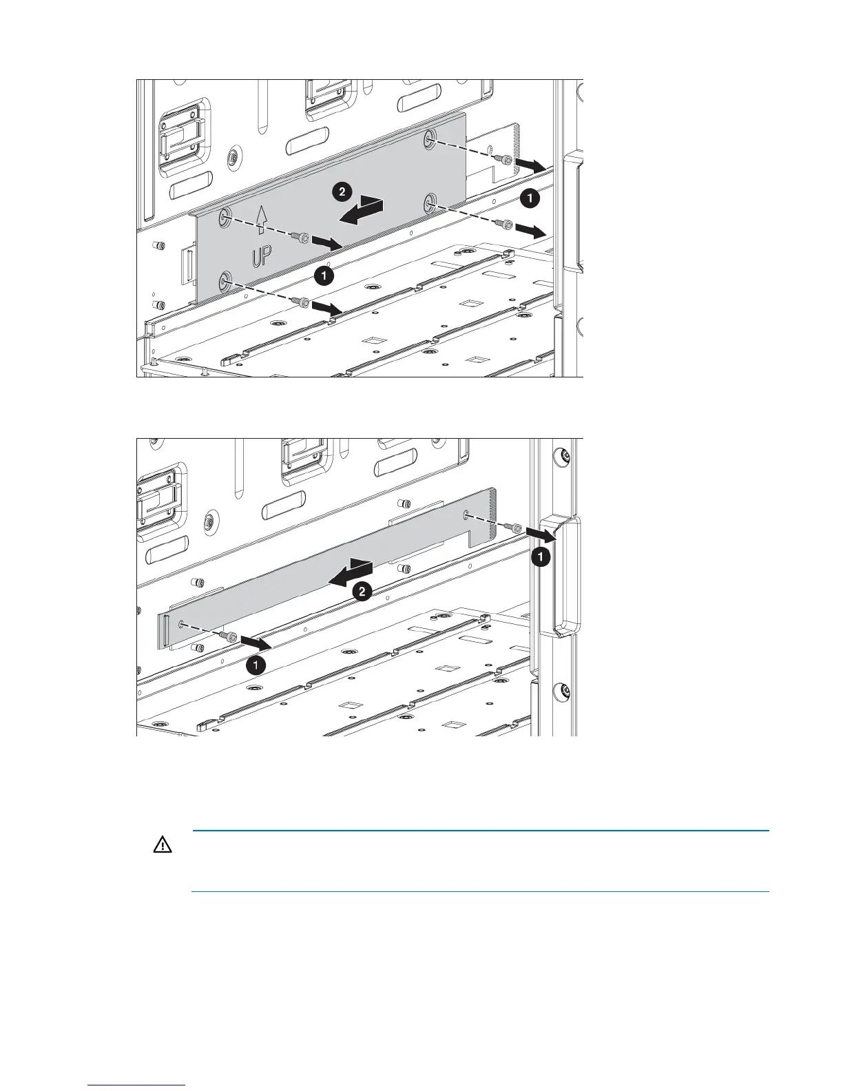
15. Remove the two slotted T-15 Torx screws that secure the interconnect board.
16. Remove the interconnect board.
To replace the component, reverse the removal procedure.
Insight Display signal pass-thru board
WARNING: To reduce the risk of damage to the midplane and component connectors, always
remove or disengage and extend all blades and power supplies approximately 8 cm (3 in) before
removing or installing the rear cage.
To remove the component:
1. Power down the server blades ("Power down the server blades or workstation blades" on page 28).
2. Power down the enclosure (on page 29).
3. Disconnect all cables.
 Loading...


