Removal and replacement procedures 47
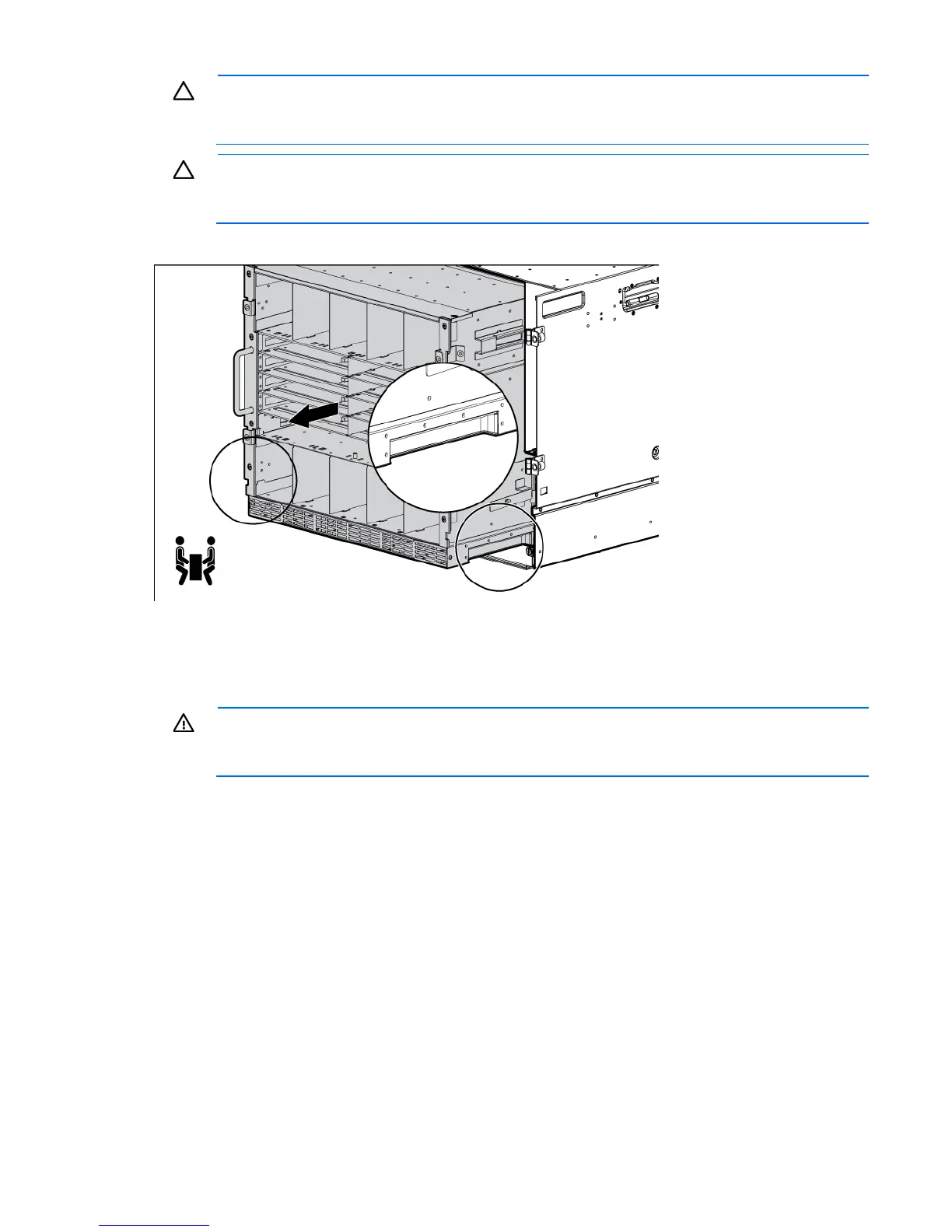
CAUTION: When removing and lifting the rear cage, always grasp the handholds as far
forward as possible. The front end of the rear cage is heavy and the handholds provide a more
balanced location to distribute the weight of the cage during lifting.
CAUTION: When removing the rear cage and midplane assembly, the connectors on the
midplane assembly are susceptible to damage. Use caution to avoid damage to the pins and
connectors.
e. Use the handholds to extend and remove the rear cage from the enclosure.
To replace the component, reverse the removal procedure.
Insight Display front-to-rear interconnect board
WARNING: To reduce the risk of damage to the midplane and component connectors, always
remove or disengage and extend all blades and power supplies approximately 8 cm (3 in) before
removing or installing the rear cage.
To remove the component:
1. Power down the server blades ("Power down the server blades or workstation blades" on page 28).
2. Power down the enclosure (on page 29).
3. Disconnect all cables.
4. Remove the half-height and full-height blades ("Half-height or full-height blade" on page 34).
5. Remove the device bay blanks ("Device bay blank" on page 31).
6. Remove the power supplies ("HP BladeSystem c7000 power supply or power supply blank" on page
30).
7. Remove the fans ("Active Cool 200 fan" on page 39).
8. Remove the interconnect switches and Pass-Thru modules ("Interconnect switch or Pass-Thru module" on
page 40).
9. Remove the Onboard Administrator modules ("Onboard Administrator" on page 43).
10. Remove the Onboard Administrator tray ("Onboard Administrator tray" on page 43).
 Loading...


