Installation steps
1. Set up the rack and its power distribution units (PDUs).
2. If applicable, install the Tape Library or Autoloader.
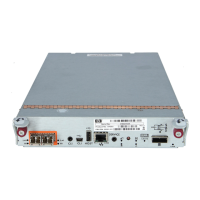
3. Install one P711m/P712m controller on each server blade.
For detailed instructions on installing the P711m/P712m, see the HP P711m/P712m Installation
Overview and HP P711/P712 Controller User Guide.
Make sure to install the P711m/P712m controller in a mezzanine slot that maps to the planned
interconnect bays of the switches. For more information about mappings, see “Device
relationships and mapping information” (page 37).
Record the slot number in which you installed the controller on the provided spaces in “Server
and P711m/P712m controller worksheet” (page 67).
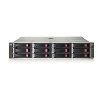
4. Install the BladeSystem c-Class enclosure and the blade devices.
For detailed instructions on installing the BladeSystem c-Class enclosure and its devices, see
the user documents for each device.
a. Before installing the BladeSystem c-Class enclosure and its component devices, record
important device information in “Solution summary worksheet” (page 66).
b. Rack the BladeSystem enclosure.
c. Install the following devices in the BladeSystem enclosure:
• Server blades with P711m/P712m controllers attached
• Power supplies
• Fans
• Onboard Administrator modules
• HP 6Gb SAS BL Switches
IMPORTANT: Be sure to install the HP 6Gb SAS BL Switches in BladeSystem
interconnect bays that map to the mezzanine slots in which the P711m/P712m
controllers were installed in the servers. For more information, see “Device
relationships and mapping information” (page 37).
d. Connect the Onboard Administrator cables and power cords.
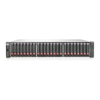
If the P2000 G3 is already racked, do not connect SAS cables between the switches and
the P2000 G3 controller enclosure at this time. Connect them only after ensuring that the
latest available firmware is installed on the P2000 G3 controllers.
e. Apply power to the rack and turn on the AC circuit breakers for the BladeSystem enclosure.
Power is automatically applied to or removed from the devices as power is applied or
removed from the BladeSystem enclosure. As the devices power on, they automatically
perform a series of Power-On Self-Tests. (POST)
Confirm successful startup of the BladeSystem enclosure and its components. View the
OA module display, the Insight Display, and device LEDs to monitor the progress of the
Power-On Self-Tests. For details, see the Onboard Administrator user guide and user
documents for the devices.
f. Complete the HP BladeSystem Insight Display installation wizard. (HP BladeSystem
c3000/c7000 Enclosure Quick Setup Instructions)
When the BladeSystem enclosure is powered up for the first time, the Insight Display
launches an installation wizard to guide you through the configuration process. After
configuring the BladeSystem enclosure, the Insight Display verifies that there are no
installation or configuration errors.
42 Installation best practices and procedures
 Loading...