4. Place the CPU heatsink on top of the processor and align the four mounting screws with the
holes 1 in the system board.
NOTE If both CPU heatsinks were removed, be sure all system board standoffs engage
with the keyholes in the chassis, be sure the system board connectors engage correctly with
the rear I/O panel, and push back on the system board while engaging the CPU heatsink
screws with the chassis standoffs. You only must push back when trying to engage the first
screw.
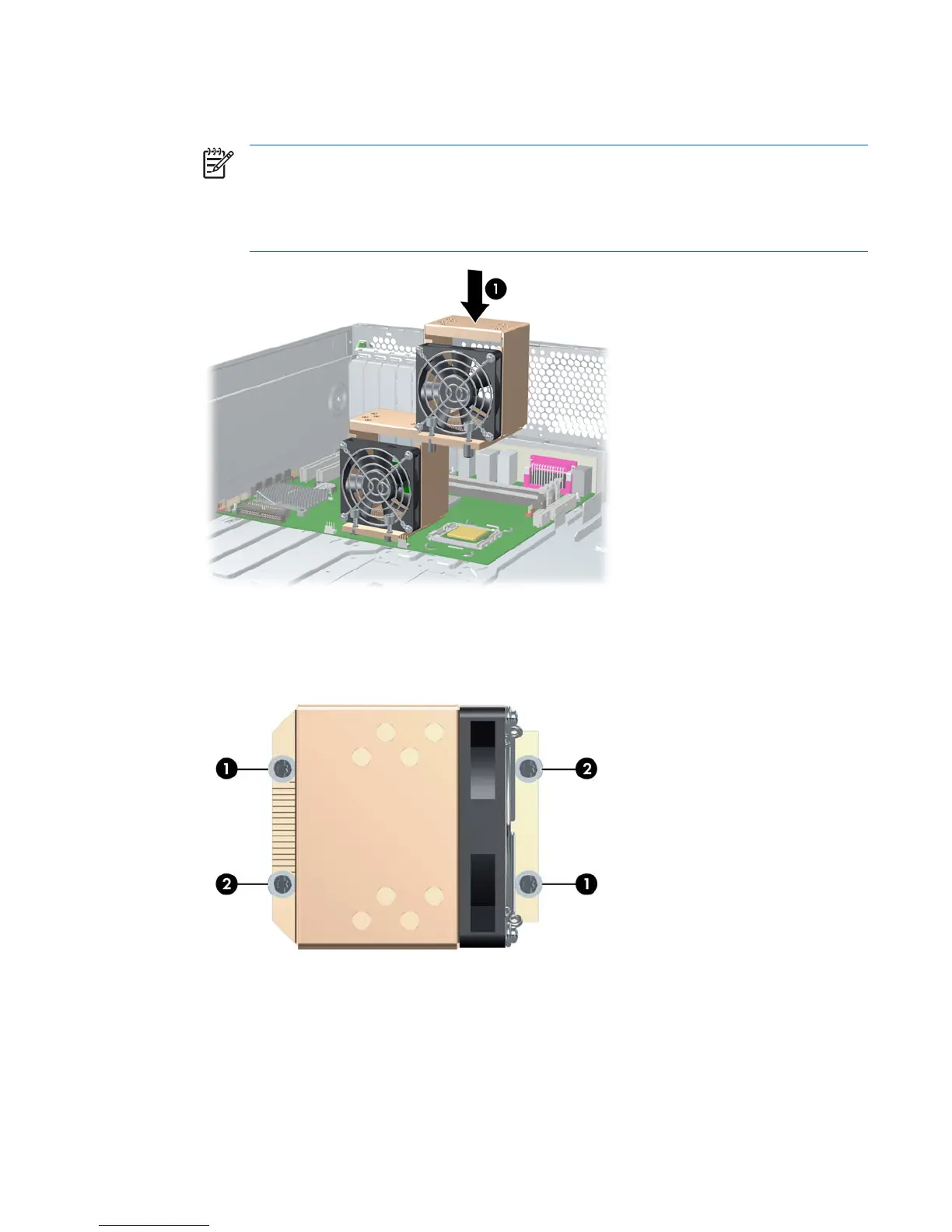
Figure 4-46 Replacing the CPU heatsink on the system board
5. Tighten the four CPU heatsink screws. First, tighten all of the screws partially so that the CPU
heatsink remains level. Next, fully tighten one pair of diagonally opposite screws 1 and fully tighten
the remaining pair 2. Tighten firmly to a torque setting of 6 in-lb.
Figure 4-47 Identifying proper screw tightening sequence
ENWW Removal and replacement of components 93
 Loading...