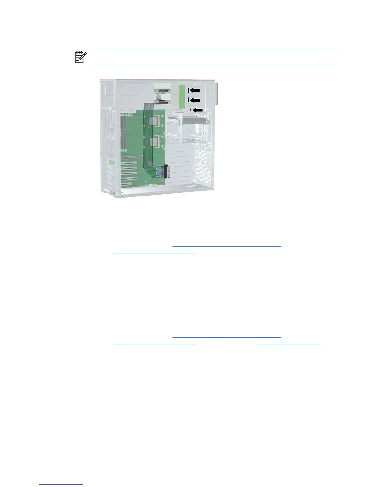
3. If you are installing more than one optical drive, route the cable as in the following image.
NOTE The optical drive cable is routed under the system board.
Figure 4-35 Connecting the optical drive cable to the system board
Replacing optical drive data cable
1. Disconnect power from the system (Predisassembly procedures on page 57), remove the side
access panel (
Side access panel on page 63), remove all expansion boards and graphics cards,
remove the CPU heatsinks, disconnect the optical IDE cable from the system board, and remove
the system board.
2. Remove the plastic ties and tape from the IDE cable, then remove the IDE cable.
3. Replace the cable and cable ties. Refer to the previous image for cable routing information.
Diskette drive (optional)
To remove a diskette drive:
1. Disconnect power from the system (
Predisassembly procedures on page 57), remove the side
access panel (
Side access panel on page 63), and the front bezel (Front Bezel on page 64).
86 Chapter 4 Removal and replacement procedures ENWW