1
Configuring Ethernet interfaces
The switch series supports Ethernet interfaces, management Ethernet interfaces, Console
interfaces, and USB interfaces. For the interface types and the number of interfaces supported by a
switch model, see the installation guide.
This document describes how to configure management Ethernet interfaces and Ethernet interfaces.
Configuring a management Ethernet interface
A management interface uses an RJ-45 connector. You can connect the interface to a PC for
software loading and system debugging, or connect it to a remote NMS for remote system
management.
Support for management Ethernet interfaces depends on the device model. For more information,
see the installation guide.
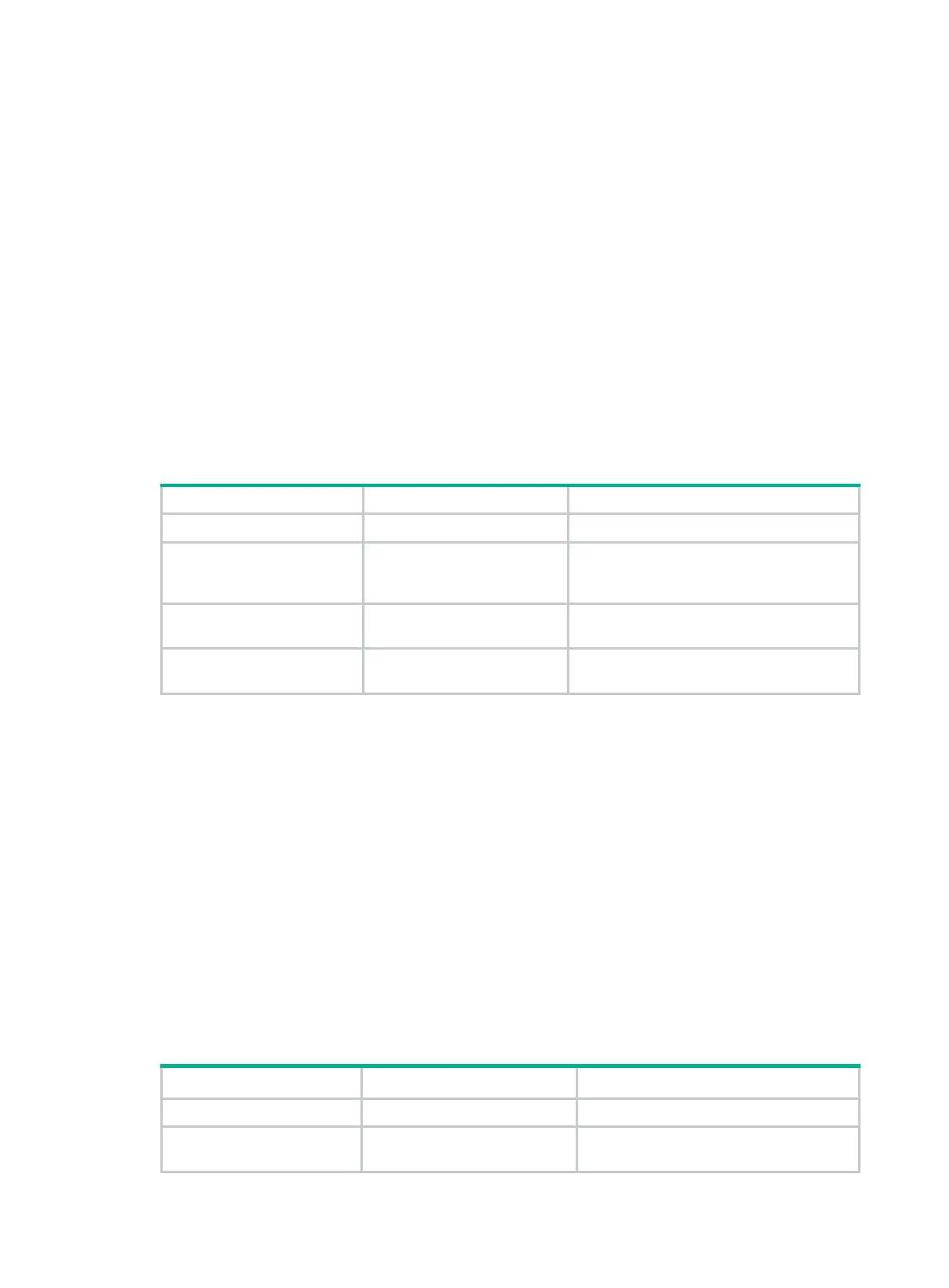
To configure a management Ethernet interface:
Step Command Remarks
1. Enter system view.
system-view
N/A
2. Enter management
Ethernet interface view.
interface
M-GigabitEthernet
interface-number
N/A
3. (Optional.) Set the
interface description.
description
text
The default setting is
M-GigabitEthernet0/0/0 Interface
.
4. (Optional.) Shut down
the interface.
shutdown
By default, the management Ethernet
interface is up.
Ethernet interface naming conventions
The Ethernet interfaces are named in the format of interface type A/B/C. The letters that follow the
interface type represent the following elements:
• A—IRF member ID. If the switch is not in an IRF fabric, A is 1 by default.
• B—Card slot number. 0 indicates the interface is a fixed interface of the switch. 1 indicates the
interface is on expansion interface-card 1. 2 indicates the interface is on expansion
interface-card 2.
• C—Port index.
Configuring common Ethernet interface settings
Configuring basic settings of an Ethernet interface
Step Command Remarks
1. Enter system view.
system-view
N/A
2. Enter Ethernet interface
view.
interface
interface-type
interface-number
N/A

 Loading...