183
• The devices can register and deregister dynamic VLANs.
• The devices can keep identical VLAN configuration for each MSTI.
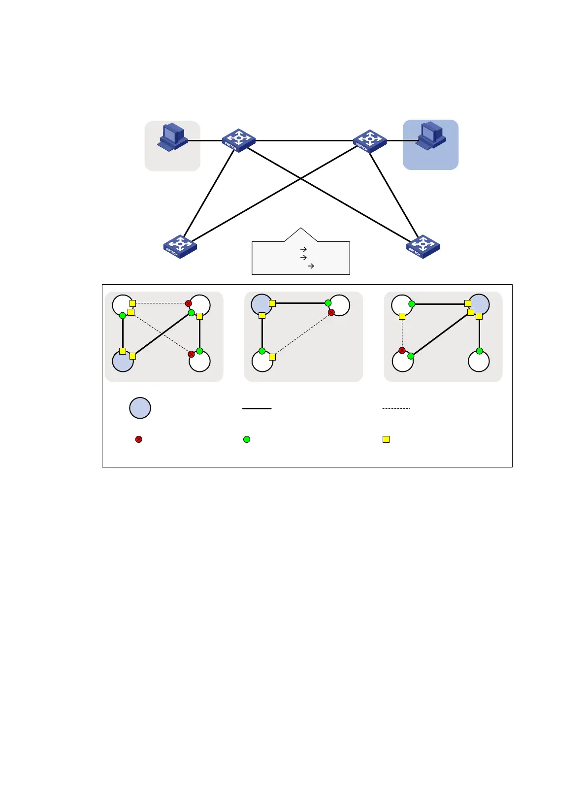
Figure 54 Network diagram
Configuration procedure
1. Configure Device A:
# Enter MST region view.
<DeviceA> system-view
[DeviceA] stp region-configuration
# Configure the MST region name, VLAN-to-instance mappings, and revision level.
[DeviceA-mst-region] region-name example
[DeviceA-mst-region] instance 1 vlan 10
[DeviceA-mst-region] instance 2 vlan 20
[DeviceA-mst-region] revision-level 0
# Manually activate the MST region configuration.
[DeviceA-mst-region] active region-configuration
[DeviceA-mst-region] quit
# Configure Device A as the primary root bridge of MSTI 1.
[DeviceA] stp instance 1 root primary
VLAN 20
Permit: all VLANs
P
e
r
mi
t
:
V
L
A
N
4
0
P
e
r
m
i
t
:
a
l
l
V
L
A
N
s
Permit: VLANs 20, 40Permit: all VLANs
Device A Device B
Device C Device D
G
E
1
/
0
/
2
G
E
1
/
0
/
1
G
E
1
/
0
/
2
G
E
1
/
0
/
1
G
E
1
/
0
/
1
G
E
1
/
0
/
1
GE1/0/3 GE1/0/3
GE
1
/
0
/
2
G
E
1
/
0
/
2
VLAN 10 MSTI 1
VLAN 20
MSTI 2
Other VLANs
MSTI 0
VLAN 10
MSTI 2
A
D
Blocked port
Root bridge
MSTI 1
B
MSTI 0
A
C
B
D
A
C
B
C
Topology of each MSTI
Root port Designated port
Link not blocked
by spanning tree
Link blocked by
spanning tree

 Loading...