71
Step Command Remarks
10. Return to system view.
quit
N/A
11. Apply the QoS policy.
• Applying the QoS policy to an interface
• Applying the QoS policy to a VLAN
• Applying the QoS policy globally
• Applying the QoS policy to a control
p
lane
Choose one of the
application destinations
as needed.
By default, a QoS policy
is not applied.
12. (Optional.) Display traffic
redirecting configuration.
display traffic behavior user-defined
[ behavior-name ]
Available in any view.
Configuration example
Network requirements
As shown in :
• Switch A is connected to Switch B through two links. Switch A and Switch B are each connected
to other devices.
• GigabitEthernet 1/0/2 of Switch A and GigabitEthernet 1/0/2 of Switch B belong to VLAN 200.
• GigabitEthernet 1/0/3 of Switch A and GigabitEthernet 1/0/3 of Switch B belong to VLAN 201.
• On Switch A, the IP address of VLAN-interface 200 is 200.1.1.1/24, and that of VLAN-interface
201 is 201.1.1.1/24.
• On Switch B, the IP address of VLAN-interface 200 is 200.1.1.2/24, and that of VLAN-interface
201 is 201.1.1.2/24.
Configure the actions of redirecting traffic to an interface to meet the following requirements:
• Packets with source IP address 2.1.1.1 received on GigabitEthernet 1/0/1 of Switch A are
forwarded to GigabitEthernet 1/0/2.
• Packets with source IP address 2.1.1.2 received on GigabitEthernet 1/0/1 of Switch A are
forwarded to GigabitEthernet 1/0/3.
• Other packets received on GigabitEthernet 1/0/1 of Switch A are forwarded according to the
routing table.
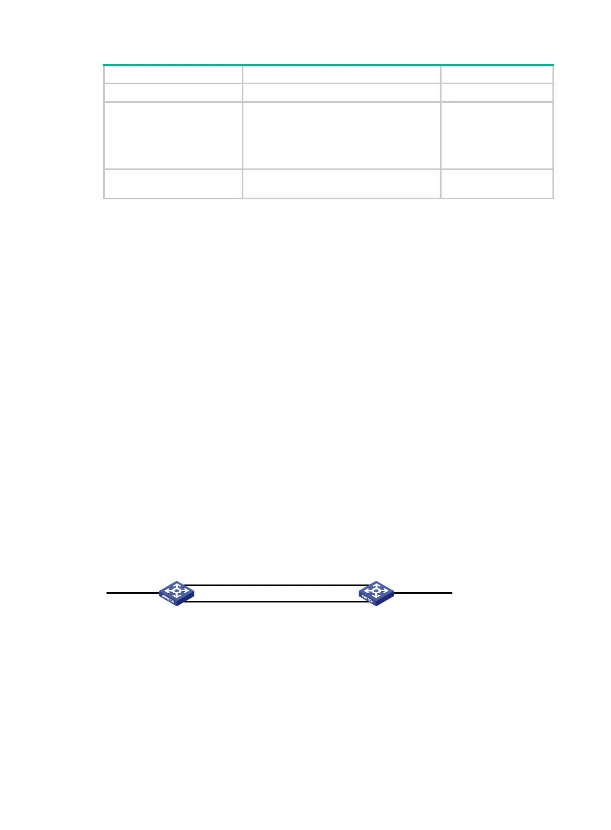
Figure 21 Network diagram
Configuration procedure
# Create basic ACL 2000, and configure a rule to match packets with source IP address 2.1.1.1.
<SwitchA> system-view
[SwitchA] acl number 2000
[SwitchA-acl-basic-2000] rule permit source 2.1.1.1 0
[SwitchA-acl-basic-2000] quit
Switch A
Switch B
GE1/0/1 FGE1/0/1
GE1/0/2
VLAN 200
Vlan-int200
200.1.1.1/24
GE1/0/3
VLAN 201
Vlan-int201
201.1.1.1/24
GE1/0/2
VLAN 200
Vlan-int200
200.1.1.2/24
GE1/0/3
VLAN 201
Vlan-int201
201.1.1.2/24

 Loading...


