Chapter 3 Electrical Installation Shenzhen Hpmont Technology Co., Ltd.
―6― HD3N-TC Series Inverter User Manual V1.0
3.1.2 Terminal
• The bare portions of the power cables must be bound with insulation tapes.
• The control circuit is basically isolated with the power circuit. Do not touch inverter after it is powered.
• Ensure that AC supply voltage is the same as rated input voltage of inverter.
• If the control circuit is connected to external devices with live touchable port, it should increase an additional
isolating barrier to ensure that voltage classification of external devices not be changed.
• If connect the communication terminal of the control circuit to the PC, choose the RS485/232 isolating converter
which meets the safety requirement.
• Only connect the relay terminal to AC 220V voltage signal. Other control terminals are strictly forbiden for this
connection.
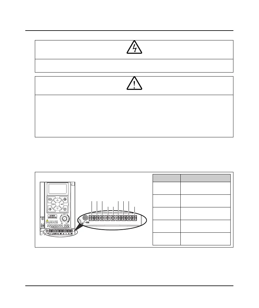
3.2 Supply and Motor Terminal
3.2.1 Terminal Description
Table 3-1 Supply and mot terminal description
Term inal Description
L1, L2, L3/N
Three-phase AC power
input terminals
L1, L3/N
Single-phase AC power
input terminals
U, V, W
Output terminals, connect
to three-phase AC motor
(+), BR
Braking resistor connection
terminals
PE
Ground terminal, connect
to the ground
Danger
arning
L1
Frame 1:
L2
L3/N
(+) BR
UVW
PE
 Loading...


