Chapter 3 Electrical Installation Shenzhen Hpmont Technology Co., Ltd.
―14― HD3N-TC Series Inverter User Manual V1.0
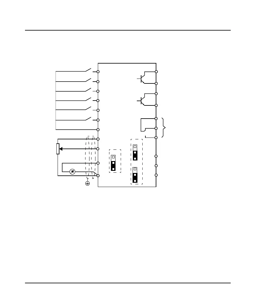
3.4.3 Control Terminal Wiring
To reduce the interference and attenuation of control signal, length of control cable should limit within
50m. There should be more than 0.3m between the control cable and the motor cable.
The control cable must be shielded cable. The analogue signal cable must be shielded twisted pair.
Figure 3-7 Frame3 / Frame4 control board connection
DI1
DO2
DO1
CME
R1A
R1C
R1B
relay output
Programmable open
collector output 1
Programmable open
collector output 2
GND
AO1
AO2
Analogue output 1
Multi-function
input 1
Multi-function
input 2
Multi-function
input 3
Multi-function
input 4
Multi-function
input 5
Multi-function
input 6
DI2
DI3
DI4
DI5
DI6
COM
AI1
AI2
+10
Analogue
input 1
Analogue
input 2
GND
Analogue output 2
COM
PE
Control board
AI2
CN2
31
AO1
CN7
31
AO2
CN8
31
 Loading...


