Chapter 5 Function Introduction Shenzhen Hpmont Technology Co., Ltd.
―60― HD3N-TC Series Inverter User Manual V1.0
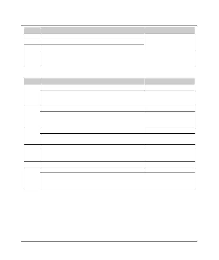
Ref. code Name Description Setting Range [Default]
F20.35 NO.2 fault interval [Actual value]
F20.36 NO.1 fault type
F20.37 NO.1 fault interval
F20.22 - F20.29 record status parameters of inverter at the last fault.
F20.30 - F20.37 record the type and interval per time of four faults before the latest. The unit of interval is
0.1 hour.
5.2.17 F23: PWM Control Parameter
Ref. code Name Description Setting Range [Default]
F23.00 Carrier frequency 1 - 8 [6kHz]
F23.00 defines the carrier frequency of PWM output wave.
• The carrier frequency will affect the running noise of the motor. The higher carrier frequency, the lower
the noise made by the motor. So properly set the carrier frequency.
F23.01 Auto adjust carrier frequency 0,1 [1]
0: Prohibited.
1: Auto adjust.
• Auto adjust the carrier frequency according to output frequency and heatsink temperature.
F23.02 PWM overshoot enable 0,1 [1]
0: Disabled.
1: Enabled.
F23.03 PWM modulation mode 0,1 [0]
0: Switch between two phase/three phase.
1: Three phase.
F23.04 Switch point 1 of PWM modulation mode 5.00 - 50.00 [5.00Hz]
F23.05 Switch point 2 of PWM modulation mode 0.00 - 50.00 [10.00Hz]
PWM modulation mode applies to V/f control and carrier frequency > 3kHz; inverter selects three phase
modulation for open loop vector control or carrier frequency ≤ 3kHz.
Note: upper limit of F23.04 = F23.05 - 2.00Hz, lower limit of F23.05 = F23.04 + 2.00Hz.
 Loading...


