Shenzhen Hpmont Technology Co., Ltd. Chapter 3 Electrical Installation
HD3N-TC Series Inverter User Manual V1.0 ―9―
3.3 Control Board for Frame1 / Frame2
3.3.1 Control Terminal
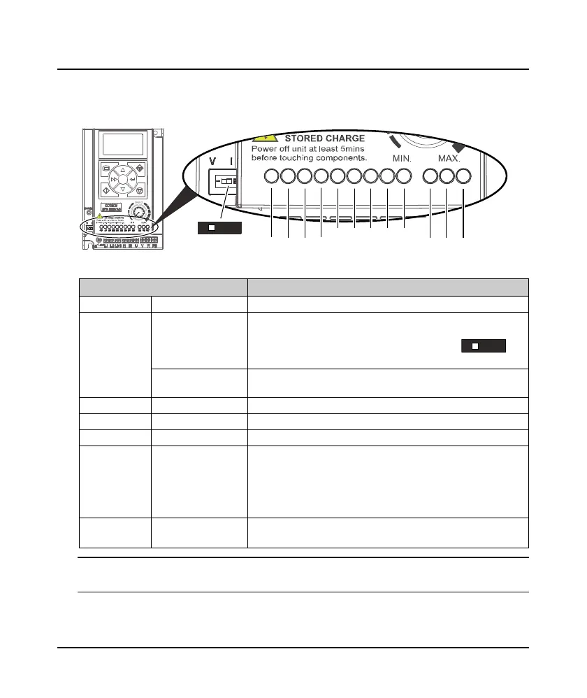
Figure 3-1 Frame1 / Frame2 control terminal
Table 3-3 Frame1 / Frame2 control terminal description
Control terminal Description
+10 External power Max. output current 100mA
AI
Analogue input
Use switch to select voltage or current input
• Voltage 0 - 10V, impedance 32kΩ (factory
setting)
• Current 0 - 20mA, impedance 500Ω
Digital input (ADI)
When AI = digital input (ADI function), receive switching signal with
over 6V
AO Analogue output Voltage 0 - 10V
GND Power supply ground Analogue and digital ground, 0V
DI1 - DI4 Digital input Valid when short-connect with GND
DO Digital output
Open collector output
• External voltage 10 - 30VDC, max. current 50mA
Or
High speed pulse output (F15.19 = No. 38)
• Max. frequency 10kHz (set by F16.26)
R1A, R1B, R1C Relay output
• Contact rating : 250VAC/3A or 30VDC/1A
• R1B, R1C normally closed (NC); R1A, R1C normally open (NO)
Note:
Limit the current within 3A if relay terminal is to connect to AC 220V voltage signal.
+10 AI AO GND
DI1 DI2 DI3 DI4 DO
R1A R1B R1C
VI
1
ON
Switch
V
I
1
ON
 Loading...


