Chapter 3 Electrical Installation Shenzhen Hpmont Technology Co., Ltd.
―12― HD3N-TC Series Inverter User Manual V1.0
Jumper Description
CN15
Analogue power supply input voltage selection:
• Pin 1 & 2 are short-connected, input voltage is +10V (factory setting);
• Pin 2 & 3 are short-connected, input voltage is +5V.
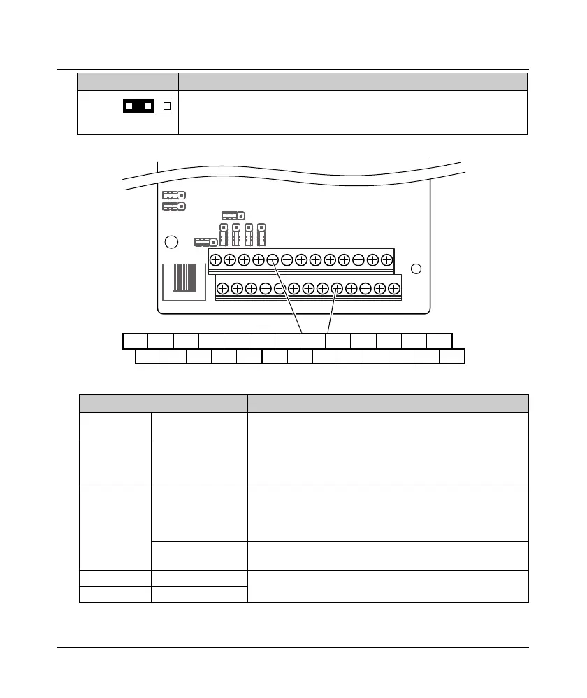
3.4.2 Control Terminal
Figure 3-6 Frame3 / Frame4 control terminal
Table 3-5 Frame3 / Frame4 control terminal description
Control terminal Description
A, B
Communication
terminal
A: 485+, B: 485-
+10V, GND
Analogue power
supply
Analogue input use +10V power supply, max. output current is 100mA
• Change to +5V by setting jumper on CN15
GND is isolated to COM
AI1, AI2
Anglogue input
AI1, AI2 input voltage: 0 - 10V (input impedance: 22kΩ)
AI2 input current: 0 - 20mA (input impedance: 500Ω)
• AI2 can select voltage / current; AI2 = current: input impedance is
selectable
Digital input (ADI)
When AI = digital input (ADI function), receive switching signal with
over 6V
AO1, AO2 Ananlogue output
Output voltage/current signal: 0 - 10V/0 - 20mA
Programmable output
GND Analogue ground
1
3
+10V
A
B
AI1 AI2 DI1 DI2 DI3 DI4 DI5 DI6 COM R1ACOM
GND
AO1 AO2
P24 SEL DO1 R1CGND COM CME DO2 R1B
Control Board
Terminal
 Loading...


