Shenzhen Hpmont Technology Co., Ltd. Chapter 3 Electrical Installation
HD3N-TC Series Inverter User Manual V1.0 ―7―
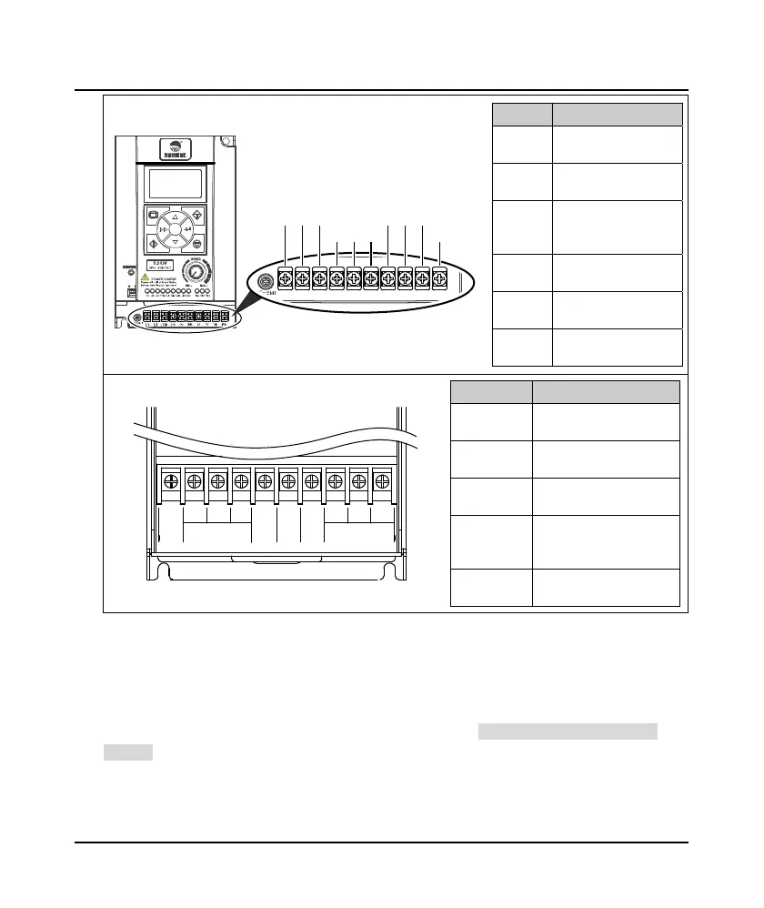
Term inal Description
L1, L2,
L3/N
Three-phase AC power
input terminals
L1, L3/N
Single-phase AC power
input terminals
U, V, W
Output terminals,
connect to three-phase
AC motor
(+), BR
Braking resistor
connection terminals
(+), (-)
DC power input
terminal
PE
Ground terminal,
connect to the ground
Term inal Description
L1, L2, L3
Three-phase AC power
input terminals
U, V, W
Output terminals, connect
to three-phase AC motor
(+), BR
Braking resistor connection
terminals
(+), (-)
DC power input
terminal;connect to
braking unit
PE
Ground terminal, connect
to the ground
3.2.2 Supply and Motor Connection
During test running, make sure motor runs forward when the forward command is enabled.
If not, switch any two of the output terminals (U/V/W) or modify F00.17 = 1 to change the motor
direction.
The supply and motor connection are shown as Table 3-2. Refer to section 3.5 Braking Resistor (on
page 19) for braking resistor.
L1 L2
L3/N
PE
WVU
BR(+) (-)
Frame 2:
L1
L2
L3 U V W
(+) (-) BR
POWER MOTOR
PE
Frame 3 / Frame 4:
 Loading...


