Chapter 3 Electrical Installation Shenzhen Hpmont Technology Co., Ltd.
―10― HD3N-TC Series Inverter User Manual V1.0
3.3.2 Control Terminal Wiring
To reduce the interference and attenuation of control signal, length of control cable should limit within
50m. There should be more than 0.3m between the control cable and the motor cable.
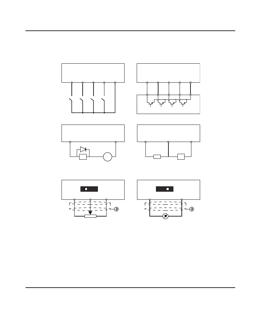
The control cable must be shielded cable. The analogue signal cable must be shielded twisted pair.
Figure 3-2 Frame1 / Frame2 digital input (DI)
Figure 3-3 Frame1 / Frame2 digital output (DO)
Figure 3-4 Frame1 / Frame2 analogue input (AI)
DI1 DI2 DI3 DI4 GND
Dry Contact NPN Contact
DI1 DI2 DI3 DI4 GND
External controller
10 - 30VDC
10kΩ
DO GND
+
-
+10 GND
DO
f
Relay coil Digital
frequenc
+10 AI GND
V
I
1
ON
AI GND
V
I
1
ON
 Loading...


