Chapter 4 Operation Instructions Shenzhen Hpmont Technology Co., Ltd.
―24― HD3N-TC Series Inverter User Manual V1.0
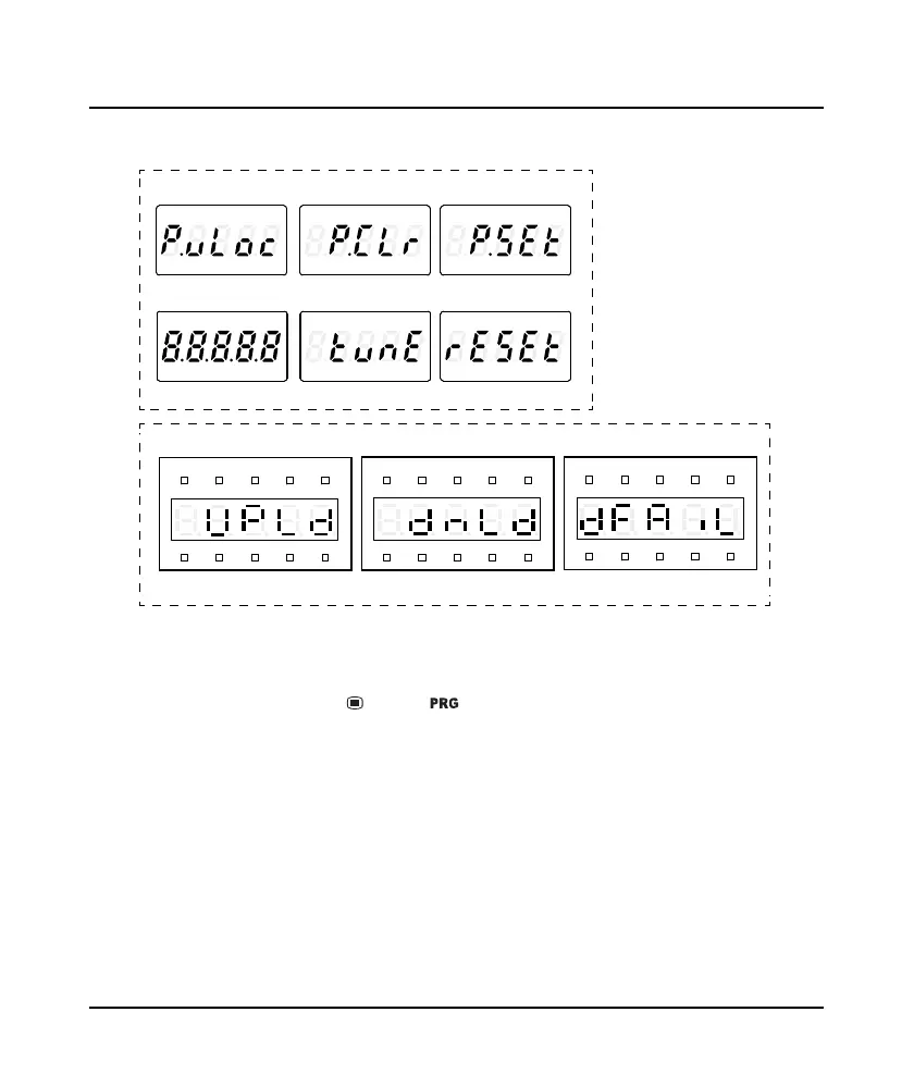
Other display status
Refer to Figure 4-4 for other display status.
Figure 4-4 Other display status
4.3 Parameter Setting
In stop / run / fault status, press button ( ) to set parameter. (If user password has been set,
refer to F00.00).
The keypad uses four-level menu: mode setting (first-level)
→
function parameter group setting
(second-level)
→
function parameter setting (third-level)
→
parameter setting (fourth-level).
Figure 4-5 is an example in LCD display and the description of buttons is shown in Table 4-1.
PW set successfullyPW has been clearedUnlock success
ResetParameter auto-tuningInitializing
Hz
AVRPM%
REVFWD ALM LO/RE LOCK
Copy para. to keypad
Hz
AVRPM%
REVFWD ALM LO/RE LOCK
Copy para. to MCB
Hz
AVRPM%
REVFWD ALM LO/RE LOCK
Failed to copy para
LED keypad
LCD keypad
FWD
Hz A V
RPM
LO/RE
%
LOCKREV
ALM
FWD
Hz A V
RPM
LO/RE
%
LOCKREV
ALM
FWD
Hz A V
RPM
LO/R E
%
LOCKREV
ALM
FWD
Hz A V
RPM
LO/R E
%
LOCKREV
ALM
FWD
Hz A V
RPM
LO/R E
%
LOCKREV
ALM
FWD
Hz A V
RPM
LO/RE
%
LOCKREV
ALM
 Loading...


