Shenzhen Hpmont Technology Co., Ltd. Chapter 4 Operation Instructions
HD3N-TC Series Inverter User Manual V1.0 ―25―
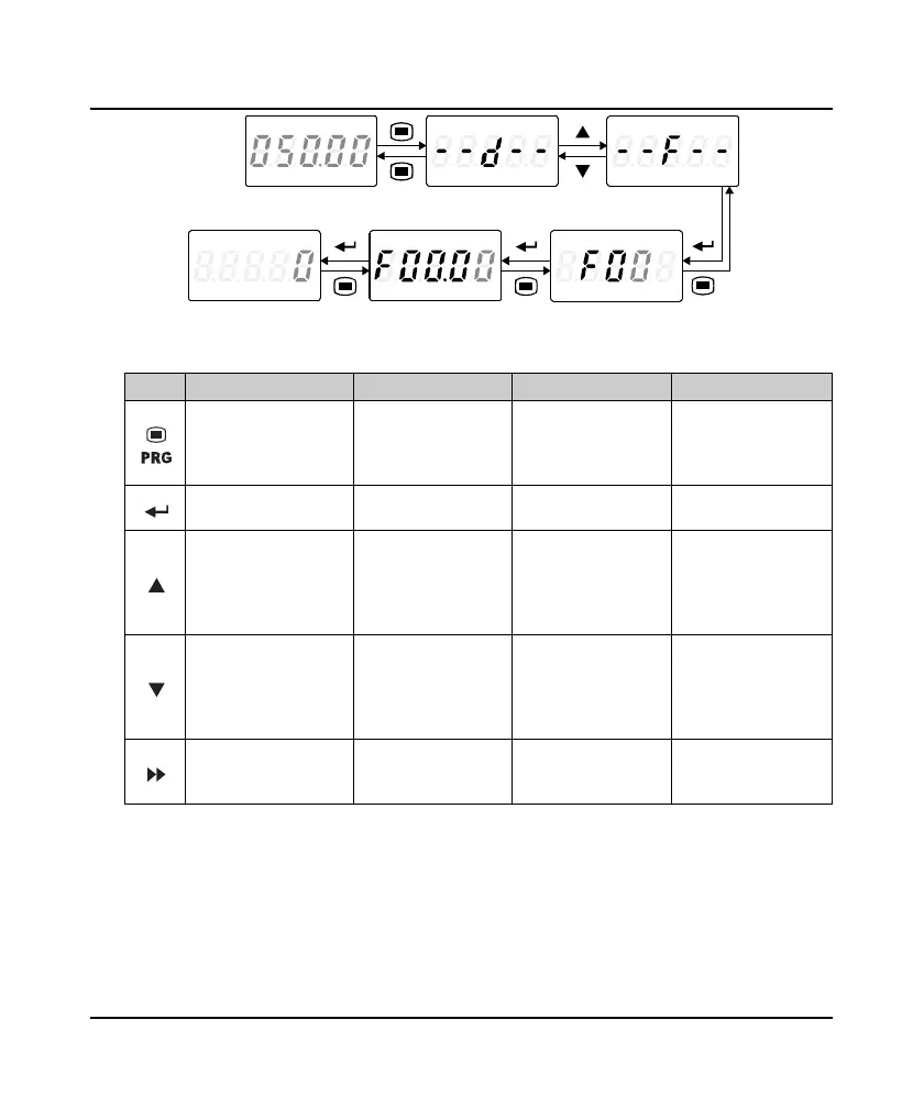
Figure 4-5 Four-level operation process
Table 4-1 Button description
Button First-level menu Second-level menu Third-level menu Fourth-level menu
Fault, return to fault
display; Fault cleared,
return to run or stop
status display
Return to first-level
menu
Return to second-level
menu
Do not save the present
value and return to
third-level
Enter second-level menu Enter third-level menu Enter fourth-level menu
Save the present value
and return to third-level
Select function group
Cycle according to d-F-y
Modify No. function.
Increase by 1 when
press this key one time
Modify the internal No.
of function group.
Increase by 1 according
to the present modified
bit
Modify function value.
Increase by 1 according
to the present modified
bit
Select function group
Cycle according to y-F-d
Modify No. function.
Decrease by 1 when
press this key one time
Modify the internal No.
of function group.
Decrease by 1 according
to the present modified
bit
Modify function value.
Decrease by 1 according
to the present modified
bit
Invalid Invalid Switch units and tens
Switch units , ten
thousands, thousands,
hundreds, tens
When setting fourth-level menu, if the parameter does not flash, it indicates that this parameter can’t
be modified. The possible reasons are as follows:
• The parameter can’t be modified, such as the actual detected parameters or recorded parameters
etc.
• Only when inverter stops can the function parameter be modified.
• Only input the correct password can edit the function parameter.
Stop status First-level menu First-level menu
hird-level menu Second-level menuFourth-level menu
FWD
H
z
AV
RPM
LO/RE
%
LOCKREV
ALM
FWD
Hz A V
RPM
LO/RE
%
LOCKREV
ALM
FWD
Hz A V
RPM
LO/R E
%
LOCKREV
ALM
FWD
Hz A V
RPM
LO/RE
%
LOCKREV
ALM
FWD
Hz A V
RPM
LO/R E
%
LOCKREV
ALM
FWD
Hz A V
RPM
LO/RE
%
LOCKREV
ALM
FWD
Hz A V
RPM
LO/R E
%
LOCKREV
ALM
 Loading...


