Shenzhen Hpmont Technology Co., Ltd. Chapter 3 Electrical Installation
HD3N-TC Series Inverter User Manual V1.0 ―17―
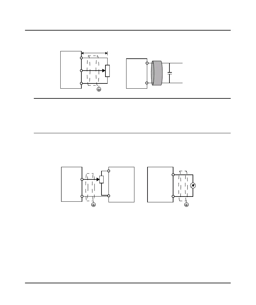
Analogue Input (AI) Connection
The AI1 is voltage input and the range is 0 - 10V, as shown in Figure 3-12.
Figure 3-12 Frame3 / Frame4 AI1 connection
Note:
1. To reduce the interference and attenuation of control signal, length of control cable should limit within 50
m, and the shield should be reliably grounded.
2. In serious interference occasions, the analogue input signal should add filter capacitor and ferrite core, as
shown in Figure 3-12.
AI2 can be selected as voltage input and the range is 0 - 10V. When selecting internal +10V of HD3N-TC,
refer to Figure 3-12. Selecting 10V external supply, refer to Figure 3-13.
AI2 can select current input and the range is 0 - 20mA, refer to Figure 3-13.
Figure 3-13 Frame3 / Frame4 AI2 connection
AI1
GND
GND
AI1
+10
PE
Potentiometer
Signal line winding
ntheferritec
re
for 2or 3turns.
Filter capacito
0.022uF/50V
Ferrite core
< 50m
AI2
GND
GND
+10V
PE PE
AI2
GND
External
wer su
ly
 Loading...


