Chapter 5 Function Introduction Shenzhen Hpmont Technology Co., Ltd.
―32― HD3N-TC Series Inverter User Manual V1.0
Ref. code Name Description Setting Range [Default]
F00.11 Command setting channel 0 - 2 [0]
0: Keypad.
•
Start and stop inverter by pressing button ( ), button ( ) and button ( ).
1: Terminal. Start and stop by using corresponding external terminals.
• DI terminal is set as FWD (DI=2), REV (DI= 3), JOGF1 (DI= 20), JOGR1 (DI=21) and JOGF2 (DI=22), refer to
group F15.
2: SCI. Start and stop by SCI port according to communication protocol.
F00.12 M key function 0 - 2 [2]
Note: Valid when LED keypad adopted only.
0: Switch running direction.
1: Switch local and remote control.
2: M key invalid.
F00.13 Starting frequency digital setting 0.00 - Upper limit frequency
[50.00Hz]
F00.10 = 0 or 1, F00.13 sets the initial frequency value.
F00.14 Frequency setting control 00 - 11 [00]
Units and tens are valid only when F00.10 = 0 or 1.
The current setting frequency value will be replaced by a new one when F00.13 has been changed.
Units: Save selection of frequency setting at power outage
• 0: Do not save at power outage.
• 1: Save at power outage.
Tens: Control selection of frequency setting at stop
• 0: Do not restore to F00.13 at stop.
• 1: Restore to F00.13 at stop.
F00.15 Jog running frequency digital setting 0.00 - Upper limit frequency
[5.00Hz]
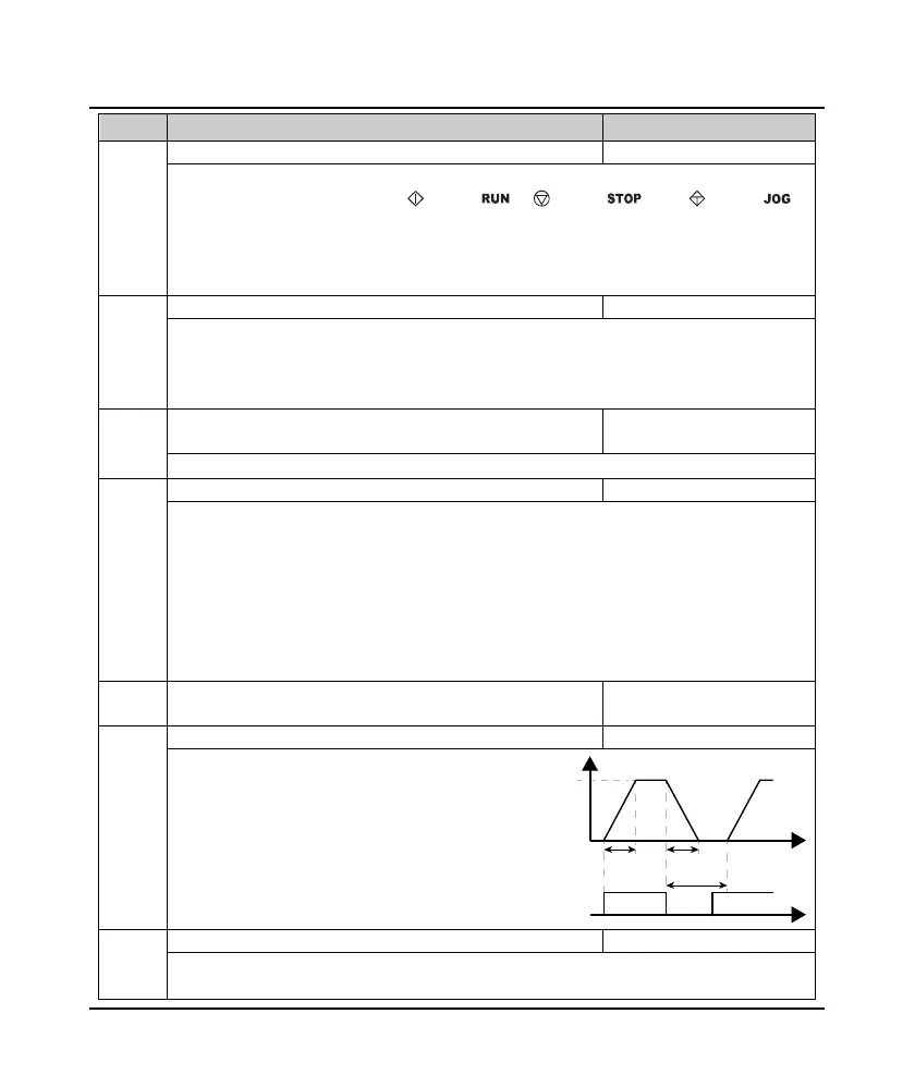
F00.16 Interval of jog running 0.0 - 100.0 [0.0s]
After cancel jog command, inverter will not
respond to jog command within F00.16.
• After the interval of jog is completed, it
immediately executes the arrived jog
command. As show in figure.
F00.17 Running direction 0,1 [0]
0: The same as running command.
1: Opposite to running command.
F00.16
F00.15
Time
Time
og command
Acc Dec
Frequency
 Loading...


