Chapter 5 Function Introduction Shenzhen Hpmont Technology Co., Ltd.
―42― HD3N-TC Series Inverter User Manual V1.0
Ref. code Name Description Setting Range [Default]
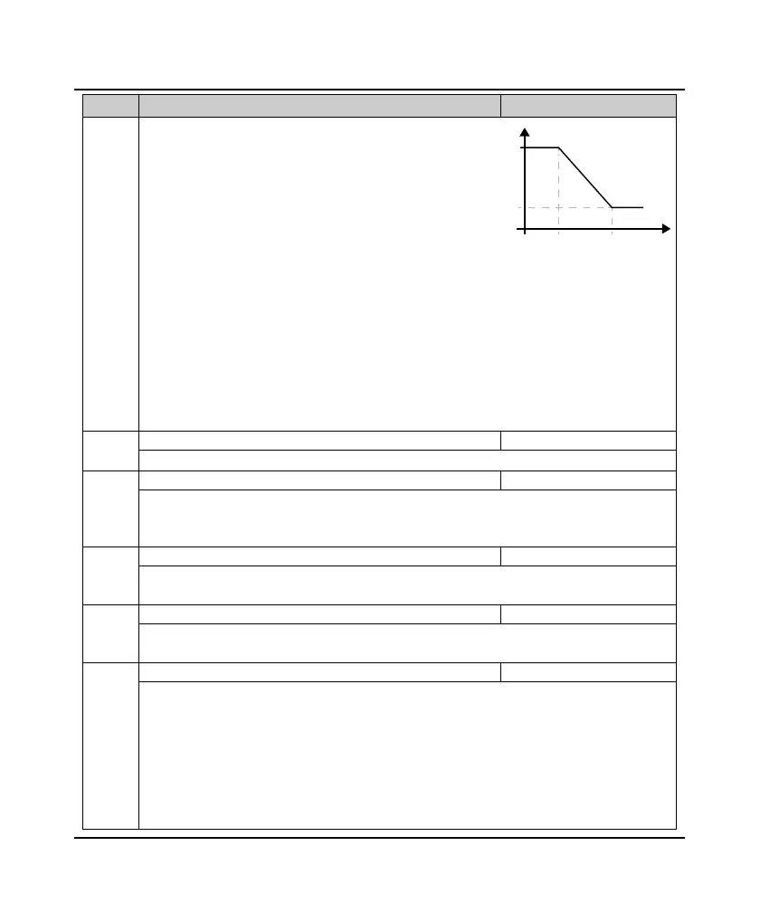
As the right figure:
• When inverter operates within 0 - F10.04, the PI parameters
of vector control are F10.00 and F10.01;
• When inverter operates above F10.05, the PI parameters of
vector control are F10.02 and F10.03;
• When inverter operates within F10.04 - F10.05, P is the linear
interpolation between F10.00 and F10.02, while I is the linear
interpolation between F10.01 and F10.03.
• The system response can be expedited through increasing proportional gain P, but oscillation may occur
if the value of P is too high.
• The system response can be expedited through decreasing ASR integral time Ti, but oscillation and big
overshoot may occur if the value of Ti is too small.
• If integral time constant=0, integral function is not effective, and speed loop is merely a propotional
regulator.
• Generally, adjust proportional gain P first to the max. condition that the system does not vibrate, and
then adjust the Ti to shorten the response time without overshoot.
• To shorten dynamic response time during low frequency running, increase proportional gain and
decrease Ti.
F10.06 ASR integral limit of motor 1 0.0 - 200.0 (F08.02) [180.0%]
It is used to limit the max. value of the vector control speed-loop integral.
F10.07 Motor 1 speed loop differential time 0.00 - 1.00 [0.00s]
Defines the vector control speed-loop differential time.
• Generally do not set F10.07. But to quicken system response, user can properly set it.
• F10.07 = 0, there is no speed-loop differential.
F10.08 Motor 1 speed loop output filter time 0.000 - 1.000 [0.000s]
It is used to filter the output of ASR regulator.
• F10.08 = 0, the speed-loop filter is unused.
F10.09 Locking selection for motor 1 torque limit 0,1 [0]
0: Do not lock.
1: All of the torque limit is same with FWD electric torque limit.
F10.10 Setting channel of motor 1 torque 0000 - 7777 [0000]
Define the setting channel of torque value.
Units: Electric torque limit channel when motor is FWD
Tens: Electric torque limit channel when motor is REV
Hundreds: Braking torque limit channel when motor is FWD
Thousands: Braking torque limit channel when motor is REV
• 0: Limit by digital setting.
• 3 - 4: AI1 - AI2.
• 7: Potentionmeter. Valid when LED keypad adopted only.
F10.04 F10.05
F10.00 /
F10.01
F10.02 /
F10.03
0
Frequenc
PI parameter
 Loading...


