SOLAR03 active and connected or active and recording
1. Switch on the instrument by pressing the ON/OFF key
2. Switch on the SOLAR03 remote unit, pair it with and connect it to the instrument as
described in § 6.2. Note the presence of the " " icon in the top right corner of the
display
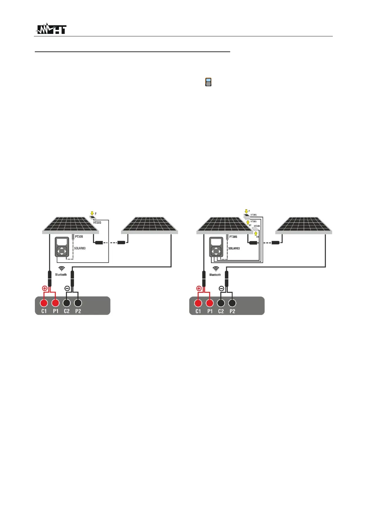
3. Connect the instrument and the SOLAR03 remote unit to the module/string being
tested as shown in Fig. 52. In detail:
➢ Connect the Negative pole output of the module/string to terminals P2, C2 and the
Positive pole output of the module/string to terminals P1, C1
➢ In case of Monofacial modules → position the reference cell HT305 onto the front
surface of module (F) and at input “INP1” and possibly temperature probe PT305
at input “INP4” of the remote unit.
➢ In case of Bifacial modules→, position the three HT305 reference cells on the
front surface of module (F), on the top back section (B T=BackTop) and on the
bottom back section (BB=BackBottom) of the module. Connect the front reference
cell (F) to input “INP1”, BT reference cell to input “INP2”, BB reference cell to input
“INP3” and possibly the temperature probe PT305 to input “INP4” of the remote
unit.
Fig. 52: Connection with remote unit SOLAR03 on Monofacial and Bifacial modules
4. In the case of Monofacial modules, the Fig. 53 screen is present on the display. The
following parameters are shown:
➢ VPN voltage between positive and negative pole of the string
➢ Module temperature (with PT305 probe connected)
➢ Module irradiance measured by reference cell HT305
➢ Display of currently selected PV module
➢ References of C1, P1, C2, P2 terminals connected to the instrument