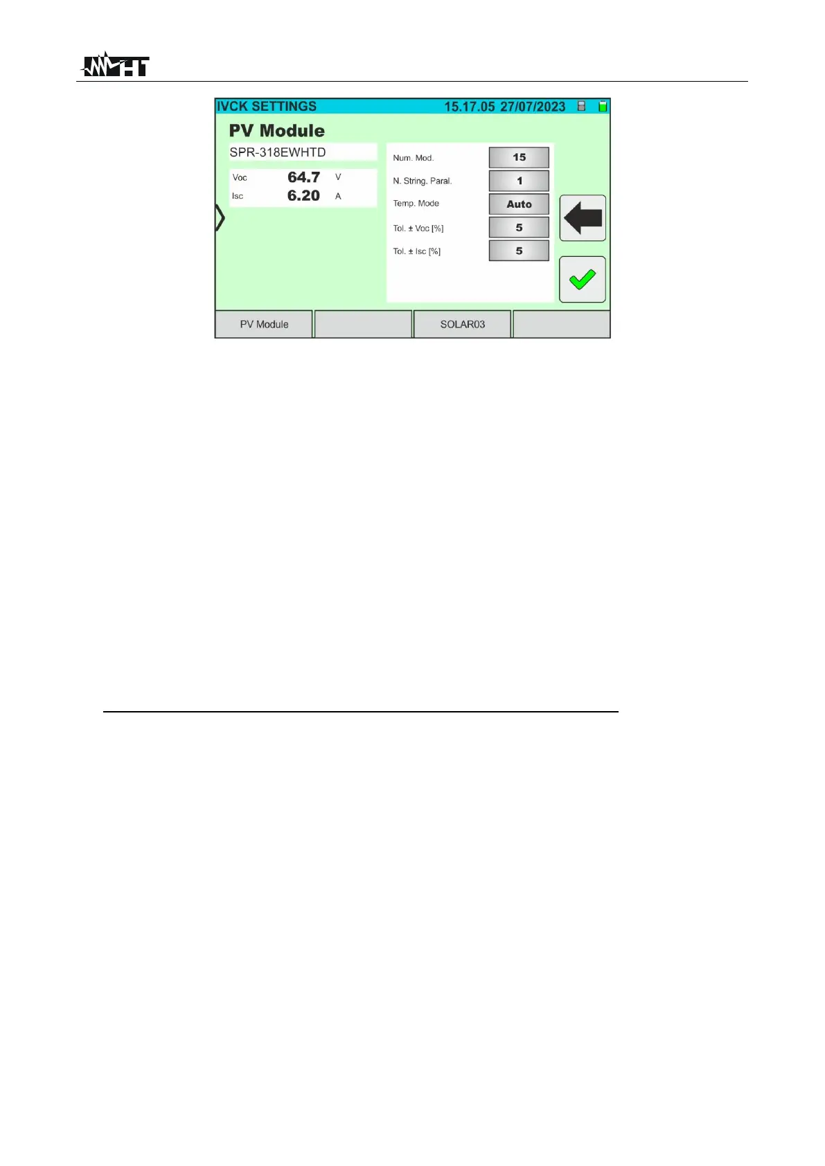
Fig. 55: I-V curve measurement parameter settings
7. Tap on the "PV Module” key to change the PV module to be tested. The instrument
opens the DB section, where a new module can be selected from the list in the DB
section (see § 6.3)
8. Scroll each of the 5 available thumb wheels to the right or left in order to set the desired
value of the following parameters:
➢ Num. Mod. → to set the number of modules in the string being tested(max. 35)
➢ N. String. Paral. → to set the number of strings in parallel (max. 5). Setting "1”
indicates the presence of only one overall string
➢ Temp. Mode → to set the module temperature measurement mode. The following
options are available: Auto (temperature calculated by the instrument based on Voc
measurement - no probe connected and recommended option), Meas.
(temperature measured via PT305 probe connected to the SOLAR03 remote unit)
➢ Tol. Voc ± [%] → setting of the percentage tolerance in the measurement of Voc in
the range: 1% ÷ 20% (typical 5%)
➢ Tol. Isc ± [%] → setting of the percentage tolerance in the measurement of Isc in
the range: 1% ÷ 20% (typical 5%)
9. In case it is necessary to record of irradiance values over time (e.g. in unstable
irradiance conditions or in case the distance between the modules and the instrument
is high), follow the steps from 7 to 11, or jump to step 12.
10. Tap on the "SOLAR03” key to access the control and management section of the
SOLAR03 remote unit (see § 6.2). Check that the remote unit is active and connected
to the instrument
11. Tap on the "Run/Stop” key to start recording on the connected remote unit; the
following screen will be displayed: