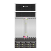
If PMs are not fully configured, power cables are routed only for the PEM interfaces whose
corresponding PMs are installed. To facilitate the deployment of new power cables during capacity
expansion of PMs, you are advised to configure the PMs from the top down and leave a filler panel in
the position where no PM is not installed.
Table 1-42 Power supply examples
Overall Power
Consumption
Table 1-43 describes recommended power supply configurations. You can choose the PM
configuration based on the actual platform.
Table 1-43 Recommended configurations
1.8.4.2 System Power Supply Architecture
NE40E-X8A uses the non-partitioned power supply architecture. NE40E-X8A backplane has
one area, which houses two power inputs converged on backplane.
-48 V DC Power Supply
As shown in Figure 1-41, the NE40E-X8A has two PEMs. Each PEM has eight inputs. There
are altogether 16 inputs (8 inputs on each of area A and area B). Each PM has two inputs. The
two inputs are from power supply areas A and B, respectively. The PM converts the power
and outputs the power to the power supply backplane. In this manner, power supply areas A
and B back up each other A maximum of 8 PMs can be configured based on the N+1 backup
mechanism.

 Loading...