The fan module of the NE40E-X3 is located at the air exhaust vent. The system draws in air
for heat dissipation, as shown in Figure 1-74 and Figure 1-75.
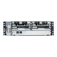
Figure 1-74 Air flow in the NE40E-X3 DC chassis
Figure 1-75 Air flow in the NE40E-X3 AC chassis
The heat dissipation system consists of the following components:
One fan module
An air intake vent and an air exhaust vent
An air filter
Fans on power modules
1.9.1.2 Fan Speed Adjustment
When the system is fully configured, temperatures reported by the temperature sensors on the
Interface boards and MPUs serve as the basis for fan speed adjustment. Table 1-96 lists
general principles.
Table 1-96 Fan Speed Adjustment Principles
Noise and Dissipation StandardsSR
 Loading...