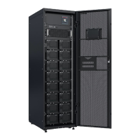
Figure 5-16 Setting the battery circuit breaker
(1) 7+7, 7+0, 8+8, and 8+0
scenarios: 250 kW < Load
power of a single battery
cabinet ≤ 300 kW; 6+6 and 6+0
scenarios: 210 kW < Load
power of a single battery
cabinet ≤ 250 kW
(2) 7+7, 7+0, 8+8, and 8+0
scenarios: 200 kW < Load
power of a single battery
cabinet ≤ 250 kW; 6+6 and 6+0
scenarios: 170 kW < Load
power of a single battery
cabinet ≤ 210 kW
(3) 7+7, 7+0, 8+8, and 8+0
scenarios: Load power of a
single battery cabinet ≤ 200
kW; 6+6 and 6+0 scenarios:
Load power of a single battery
cabinet ≤ 170 kW
5.6.3.1 UPS Without a Neutral Wire
Procedure
Step 1 Remove the cable gland nuts and sealing plugs from the top of the cabinet based
on site requirements.
Figure 5-17 Top cable glands
(1) Positive cable (gland: M63)
(2) Positive cable (gland: M50) (3) Neutral cable (gland: M50)
(4) Negative cable (gland:
M63)
(5) Neutral cable (gland: M63) (6) Negative cable (gland:
M50)
Step 2 Cut cables and crimp terminals.
1. Pull a cable to the copper bar to be connected, measure the cable length, and
mark the position where the cable needs to be cut and the direction of the DT
terminal.
SmartLi 3.0
User Manual (Short-Term Backup Power) 5 Installation and Cable Connection
Issue 10 (2024-01-31) Copyright © Huawei Digital Power Technologies Co., Ltd. 74

 Loading...


