English – 39
Check before adjusting
1. Place a tool for measuring wheel speed under
one side of the machine. Make sure the raised
wheels do not make contact with the ground or
other xed objects. Make sure the other two
wheels are in contact with the ground or have
been prevented from rotating in some other way.
For more information, refer to “3 Service tools”
on page 9.
2. Mark the free rolling wheels with reective tape
or equivalent.
3. Remove the cover over the rear transmission.
1
2
8
7
9
4
3
5
6
1. Basic speed locknut N=17
2. Basic speed adjuster nut N=17
3. Joint bearing 2
4. Override spring
5. Basic speed adjustment screw (black) N=20
6. Joint bearing 1
7. Slewing speed locknut N=14
8. Slewing speed adjustment screw N=14
9. Recoil spring
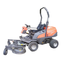
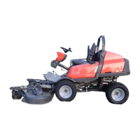
5.2.10 Wheel speed
The relationship between the rear and front wheel speed should always be the same or constantly faster on the
rear wheels than the front wheels. Wheel speed must however be max 3% faster on the rear wheels than the
front wheels. If the relationship between the wheels differs from this value, the machine may lack power and go
slower than normal. Wear on transmission components may also be greater than is necessary.
The wheel rotation on the front axle should be between around 330-350 RPM with the wheel on one side
locked. If this value is not attained, the hydrostatic cable can be adjusted. See section “5.2.9 Hydrostatic cable”
on page 37.
A. 442 ±1 mm
B. 20 mm
C. Locknut
D. Locknut
4. Make sure the adjustment screw (5) is in the
joint bearing (6).
5. Check that the control stay under the machine is
not damaged.
6. If the stay has been damaged, measure the
distance between the joint bearings (A) and set
the correct dimension. If there is any deviation,
the adjusting rod must be straightened or
replaced. Make sure the locknuts (C, D) are
tightened with 40±5 Nm.
7. Warm up the transmission until the wheel speed
has stabilized.
8. Make sure the joint bearing (3) is not in contact
with the thrust washers.
Tools Dimension
Torx T30
Tool for measuring
wheel speed
Laser meter
Reective tape
Combination wrench 14 mm x2
Combination wrench 15 mm
Combination wrench 17 mm x2
Propulsion

 Loading...