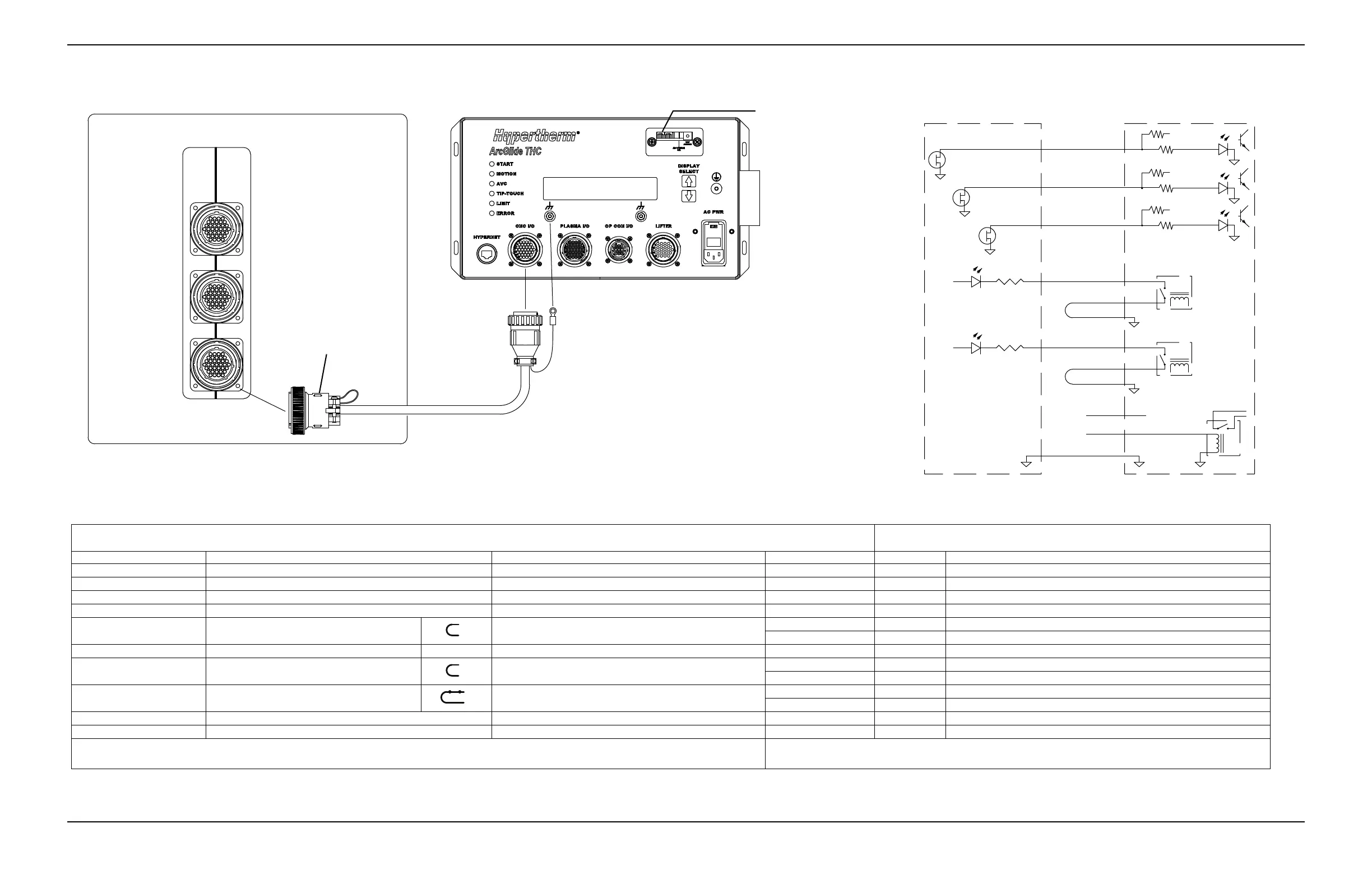
Picopath CNC end A
CNC I/O cable
Picopath interface CNC
I/O
Axes 1, 2
Axes 3, 4
ArcGlide control module
ArcGlide control module end B
Set dry contacts by sliding
the switch to D.
Picopath connector kit (228490)
End A of the Hypertherm ArcGlide CNC I/O cable is terminated during installation and will work only if the I/O setup in Phoenix software corresponds to the setup
described in this half of this table.
End B of the Hypertherm ArcGlide CNC I/O cable is terminated at the
factory as described in this half of the table.
Pin No. Function* Phoenix mapping name Wire color* Pin No. Signal
32 Output 12 Cut Control Red 1 Cycle start input +
31 Output 11 Hold Ignition Blue 7 IHS sync input +
30 Output 10 Torch Height Disable Green 5 AVC disable input +
12 Input 12** Cut/Mark Sense Green 17 Machine motion output A
Jumper blue and red, pins 18 and 29.
Red 18 Machine motion output B
Blue 29 Common
11 Input 11** Torch Collision Yellow 21 Torch breakaway output A
Jumper red and green, pins 22 and 30.
Red 22 Torch breakaway output B
Green 30 Common
External switch
Satisfy with switch or jumper.
Orange 25 Interlock input + **
Red 26 Interlock input - **
37 24 V common Yellow 31 Common
Backshell Chassis ground Drain wire Ring terminal Chassis ground
* This example uses CNC outputs 10, 11, 12, and inputs 11 and 12. Assign the I/O points in the Phoenix software.
** Set ArcGlide plasma inputs to dry (D) using the plasma input switch on the THC processor board in the control module.
* Multiple wires are the same color. Verify pin-to-pin connections before plugging cables into equipment.
** ArcGlide interlock must be closed to enable ArcGlide motion.