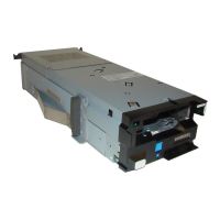
Table 18. Ports on the utility node
Item number Feature Description
1 Power supply unit Provides power supply to the
system
2 VGA port Provides a video connection to
the BMC
3 SSR port Provides one RJ45 10 GbE port
for SSR connection
4 Management port Provides one RJ-45 10 GbE
port for management/campus
connection
5 BMC Display Port Provides one RJ45 1 GbE port for
BMC connection.
6 USB connector Reserved for service
7 USB connector Provides for keyboard connection
8 Power supply unit Provides power supply to the
system
9 4-port GbE adapter Provides four port management
network card
10 CX-6 VPI adapter Provides two port high
speed cluster management for
ethernet/IB connection
11 Riser C Provides for riser card C to plug in
CX-6 network adapter
12 Riser D Provides for riser card D to plug
in 4-port GbE adapter.
Onboard Ethernet ports on the server provide system management and BMC connections. The 1 Gbps
Ethernet ports on the server use RJ45 connection.
The utility node has two Gen4 x16 PCIe slots to support optional host interface adapters. The host
interface adapters can be supported in any of the interface slots. The following table provides an overview
of the host interface adapters.
Table 19. Summary of supported host interface adapters
Protocol Feature code Ports FRU part
number
Quantity supported
CX-6 VPI network
adapter
<TBD> 2 per adapter <TBD> 1
Chapter 3. Planning for hardware39