Reviewing IBM Storage Scale System 3500 location guidelines
Consult these guidelines when you plan the location of IBM Storage Scale System 3500 and any existing
IBM Storage Scale System in your environment, including any IBM Storage Scale client or protocol node.
IBM Storage Scale System 3500 contains two server canisters. Each IBM Storage Scale System 3500
cluster consists of the following components:
• One or more IBM Storage Scale System 3500 systems – each system requires 2U (standard rack units)
in a rack.
• One EMS node - requires 2U space in a rack.
• 1 GbE Network switch for management network - requires 1U in rack.
• High-Speed InniBand or Ethernet network for internode communication – requires 1U space in rack.
IBM Storage Scale System 3500 model
The model contains two hot swappable server canisters that have one CPU each.
Planning for power for server canister
Each enclosure is provided power through two power supplies. Either of the power module can power the
enclosure independently if there is a loss of input power to the other power supply in the enclosure.
Plan to connect the power cords of the power supplies on the left side of the enclosures (when viewed
from the rear) to one power source, and connect the power cords of the power supplies on the right side
of the enclosures to another power source.
Attention:
The power cords are the main power disconnect. Ensure that the socket outlets are
located near the equipment and are easily accessible.
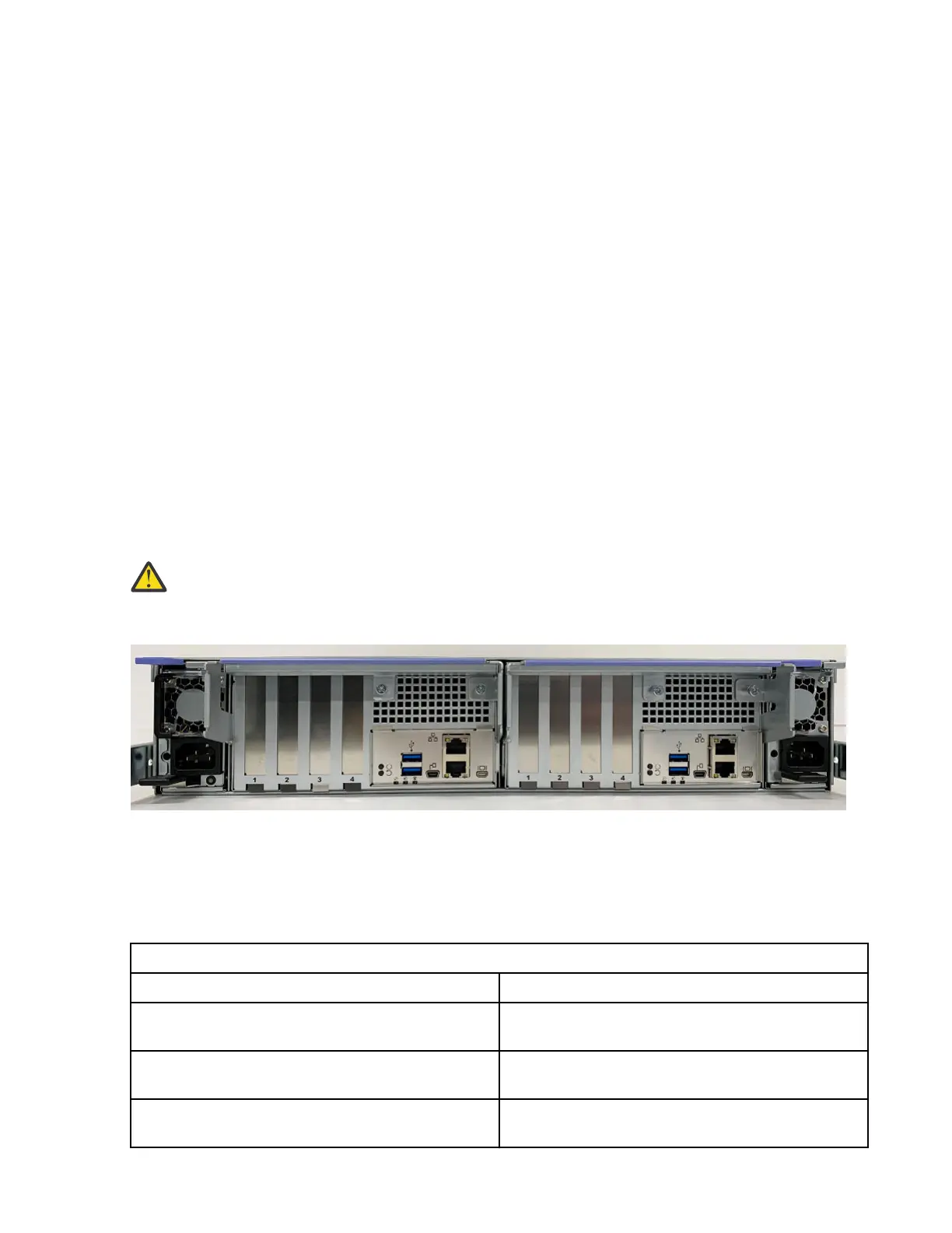
The following gure shows the rear view of an IBM Storage Scale System 3500. Each power module is
located on the sides of IBM Storage Scale System 3500.
Figure 10. Rear view of an IBM Storage Scale System 3500
Planning for cable connections to PDUs
Each enclosure must be connected to a pair of power outlets by selecting appropriate feature codes while
ordering the system. The following table lists the feature codes of the power cords.
Table 4. Power cord feature codes
Feature codes Description
6577 Power Cable - Drawer to IBM PDU, 200-240V/10A
C13/C14
END3 Power Cable - Drawer to IBM PDU, 200-240V/10A
C13/C14
ELC5 Power Cable - Drawer to IBM PDU (250V/10A)
C13/C20
26IBM Storage Scale System 3500: Hardware Planning and Installation Guide