Figures
1. Front view of IBM Storage Scale System 3500.......................................................................................... 17
2. Rear view of IBM Storage Scale System 3500........................................................................................... 17
3. IBM Storage Scale System 3500 Networking............................................................................................ 19
4. Network topology........................................................................................................................................20
5. IBM Storage Scale System 3500 high-level architecture and topology....................................................21
6. Performance conguration......................................................................................................................... 22
7. Front view of IBM Storage Scale System 3500 with drives installed........................................................ 22
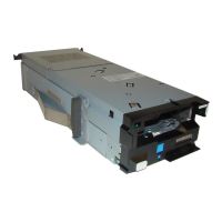
8. Power module..............................................................................................................................................23
9. SSR access port...........................................................................................................................................23
10. Rear view of an IBM Storage Scale System 3500.................................................................................... 26
11. Service envelope illustration (Dimensions in millimeters)...................................................................... 34
12. Sample illustration to show space around the rack.................................................................................35
13. Acoustical declaration with noise hazard notice......................................................................................36
14. Orientation of ports on the utility node.................................................................................................... 38
15. Rail assembly............................................................................................................................................ 43
16. Removal of square post screw..................................................................................................................43
17. Installation of round post screw...............................................................................................................44
18. Removal of the inner rail...........................................................................................................................44
19. Release tab................................................................................................................................................44
20. Installation of left rear bracket.................................................................................................................45
21. Securing the rear end of the left outer rail............................................................................................... 45
22. Removal of the middle screw................................................................................................................... 45
23. Installation of the front bracket................................................................................................................46
vii