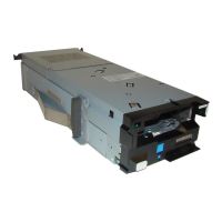
Figure 72. Releasing the metal latches
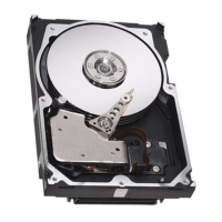
b) Press the lock button, and pull the rail outside of the rack assembly.
Figure 73. Pressing the lock button
3. Install the switch. For more information about installation, see “Installation overview” on page 76.
Replacing a power supply unit
The 5149-N64 switch has two replaceable power supply units (PSUs) in a redundant conguration. Only
one healthy PSU is required for the switch to function.
Before removing a PSU, ensure that the other PSU is connected and shows a solid green LED.
1. Remove a power cord from a PSU.
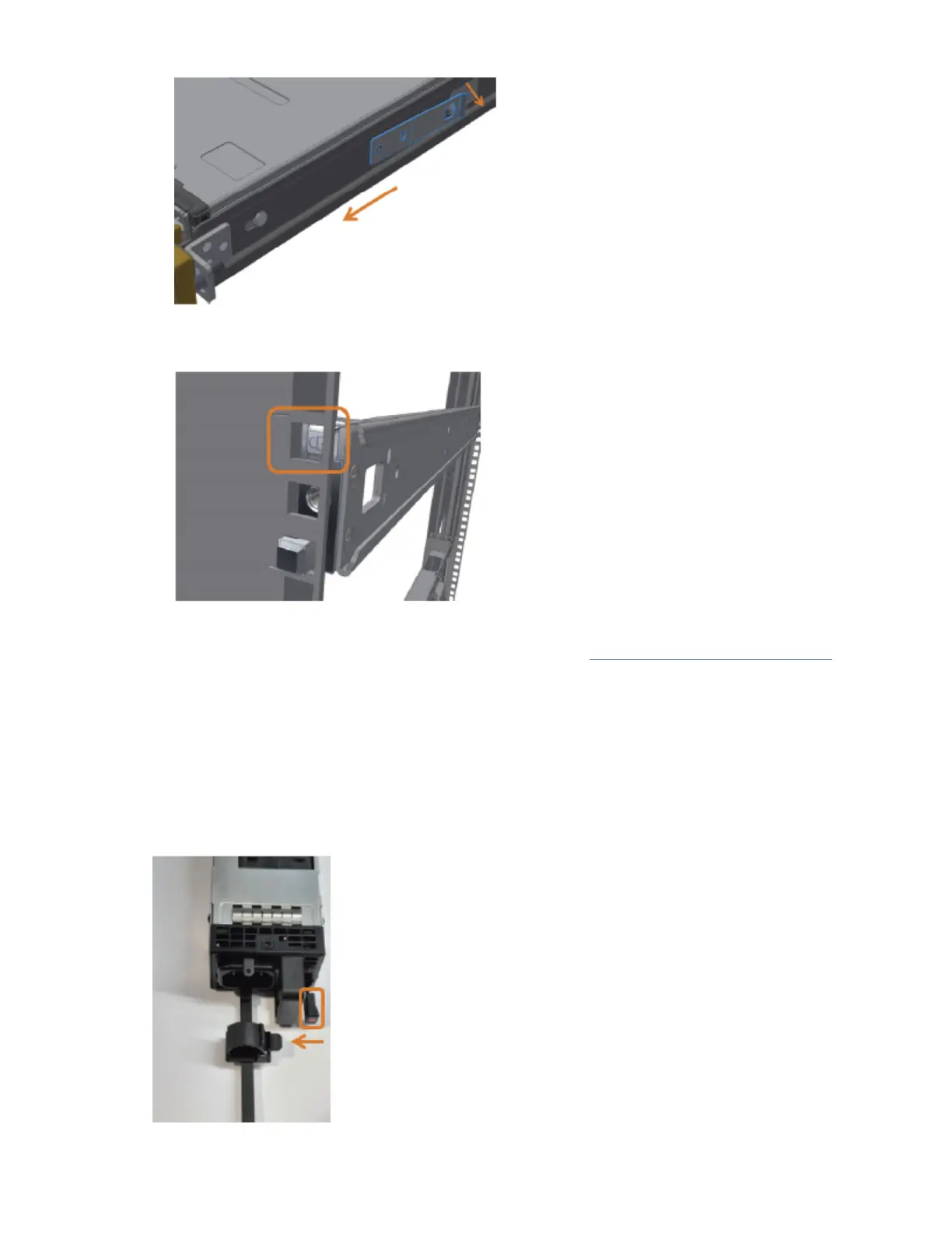
2. Push the release latch while pulling the handle toward you. As the power supply unit unseats, the PSU
status LED turns off.
Figure 74. Releasing latch while pulling the handle
Appendix C. The 5149-N64 switch
83