Includes system rails that attach to the switch, and rack rails that attach to the rack.
• Four power cables
Type C14 to C15
• Two PSU cable retainers
• 32 dust caps
• One environmental notice user guide
• One repair identication tag
Installing the 5149-N64 switch
Complete this procedure to install the 5149-N64 switch.
Two people are required to lift the switch above 1.4 m (57 in). Check the TDA document to identify where
the switch will be installed. Installation locations at 32U and higher require two people to lift the switch.
For installation locations less than 32U, one person can safely lift the switch.
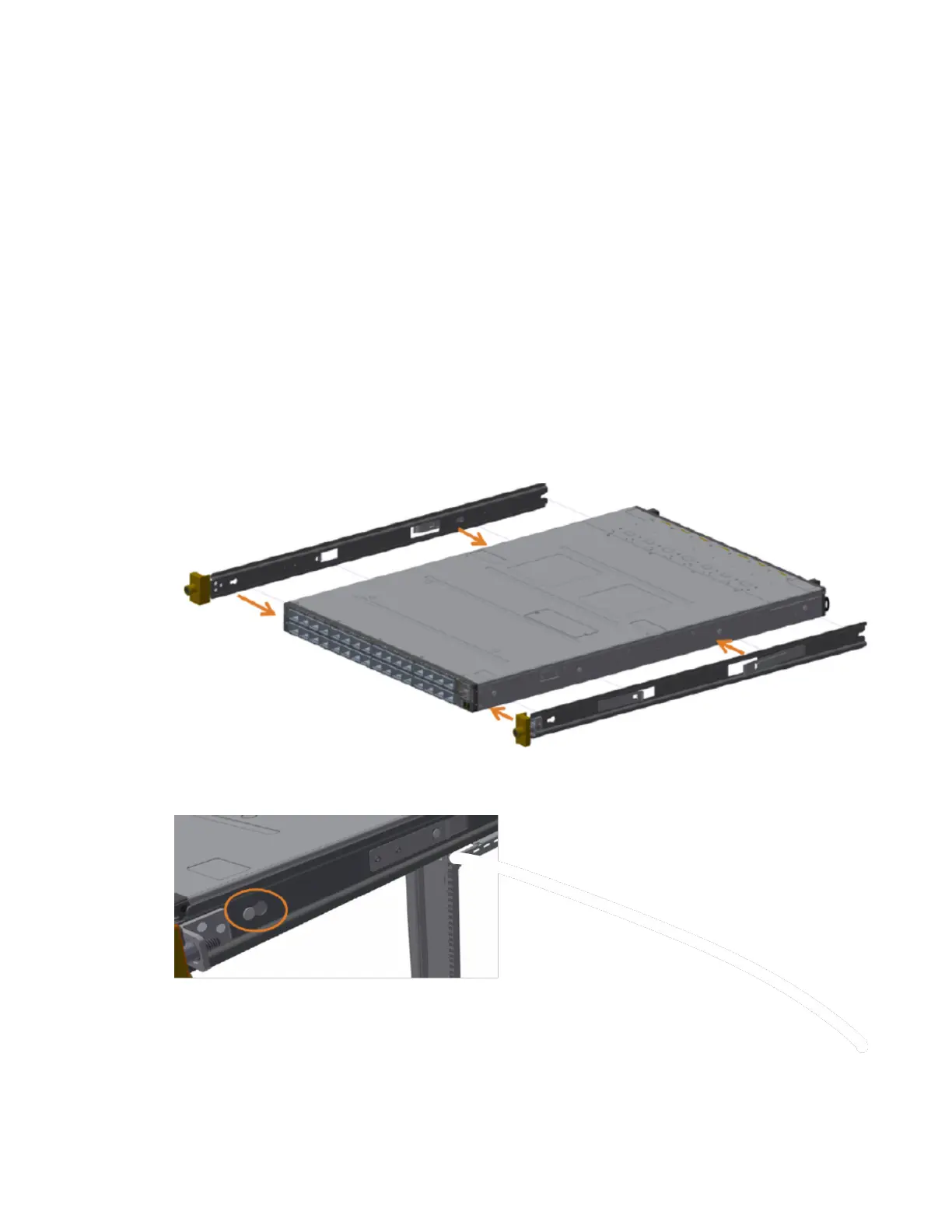
1. Attach the left and right system rails to the switch.
a) Align the switch and the system rails so that the system chassis pins align with the button holes on
the rails and press the rails to the switch.
b) Slide the rails toward the power side of the switch.
Figure 61. The 5149-N64 switch and rails alignment
The following gure shows a closeup of a rail secured to the switch:
Figure 62. A rail secured to the 5149-N64 switch
2. Attach the rack rails to the rack.
a) Insert the rack rails into the back of the rack at an angle, then rotate the rails to align with the front
rack post.
Appendix C. The 5149-N64 switch
77